EMIT User Guide

Overview


The Emissions and Modeling Impacts Tool (EMIT) is a standalone component of the broader Air Resources Toolkit. The toolkit was developed by the Bureau of Land Management (BLM) to aid individuals needing to prepare air resources related National Environmental Policy Act (NEPA) analysis to support various BLM managed activities. EMIT is a user-friendly single page web application designed to generate project specific emissions inventories and impacts analyses using a variety of regulatory tools and methods. EMIT is based on many years and iterations of emissions inventory tool development and NEPA analyses that have been widely used and accepted as state of the practice appropriate.

This User’s Guide was designed to guide users through the process of analyzing emission-generating projects. This guide also provides information on the equations used by EMIT in calculating emissions and shows how the inputs provided via EMIT are used in these equations.

EMIT provides emissions estimates for direct and indirect pollutants for each of the following categories:

  • Criteria Pollutants
    • Particulate Matter with an Aerodynamic Diameter of 10 microns or less (PM10)

    • Particulate Matter with an Aerodynamic Diameter of 2.5 microns or less (PM2.5)

    • Nitrogen Oxides (NOX)

    • Carbon Monoxide (CO)

    • Sulfur Dioxide (SO2)

  • Volatile Organic Compounds (VOCs)
    • VOCs are numerous, varied, and ubiquitous through the natural and man-made environments

    • Carbon based chemicals with low boiling point that readily evaporate or sublimate at room temperatures

    • Can participate in smog forming reactions (ozone precursor)
    • EMIT presents VOCs as an aggregated total (i.e., no speciation, or reactivity indexing is provided)


  • Hazardous Air Pollutants (HAPs)
    • HAPs are known to cause cancer and other serious health impacts

    • 187 specific chemicals and several metal compounds (e.g., cadmium, mercury, chromium, and lead)

    • EMIT presents HAPs as an aggregated total

  • Greenhouse Gases (GHGs)
    • Carbon Dioxide (CO2)

    • Methane (CH4)

    • Nitrous Oxide (N2O)

    • EMIT uses Global Warming Potentials (GWPs) for the listed GHGs as follows: 1, 36, 298

EMIT Navigation

User navigation throughout the EMIT model is described in this section.

Panels

The EMIT screen is consistently divided into three panels throughout all applications of the model: the route navigation panel, the screen navigation panel, and the main screen. The three panels of the screen are identified in Figure 1, which is a screenshot of the opening EMIT display.


Figure 1. Screenshot Showing EMIT Panels

The panel on the left, the route navigation panel, allows the user to select one of six model routes. The six routes that the user can select in this panel are:

  • Modules—Use to create a new project or select an existing project and select the EMIT module.

  • Module Forms—Use to enter the data specific to the project.

  • Emissions—Use to tabulate and display the resulting project emissions.

  • Modeling—Use to create input files for dispersion modeling.

  • Reports—Use to summarize the project data and create conformity reports.

  • Settings—[TBD]

Typically, a user would follow each of these model routes sequentially in the process of evaluating a project and determining whether it meets the General Conformity requirements established under the NEPA.

The panel to the right of the route navigation panel is the screen navigation panel. The user selection on this panel determines the information included on the main screen. The user can collapse the route navigation panel by toggling the three horizontal bars at the top left of the screen navigation panel.

The main screen is where the user enters and evaluates the project data.

Project Actions

When creating a new project, via the Modules route in EMIT, there are four actions that can be taken with each project listed. The project action controls are shown in Figure 2, which represents an EMIT screenshot of the main screen, when the Modules route is selected in the route navigation panel.


Figure 2. Location of Project Action Controls

  • Load:  A project must be loaded before any project data can be entered in the data forms. Only one project can be loaded at a time and is considered to be the active project. In order to load or delete another project, there must be no active project. If there is an active project, close the active project using the close icon in the Right Drawer Control from the Module Forms route and then load or delete the desired project.

  • Copy:  This copies the listed project and all data associated with the project to a new project. The user will need to enter new project information for the copied project, but all associated data from the original project will be carried over.

  • Delete:  This deletes the selected project. As noted above, all projects must be closed before any project can be deleted.

  • Admin:  Selecting this icon will bring up a panel on the right of the screen with administrative information and options

Once a project has been loaded, the user can then move to fill in data associated with the project through the Module Forms route in EMIT.

Right Drawer and Tab Controls

When the Module Forms route is selected, a set of additional actions are available to the user through the right drawer controls, which appear on the right center side of the main screen as shown in Figure 2.


Figure 3. Location of EMIT Right Drawer Controls and Tab Controls

The actions associated with clicking on each of these control icons are described below.

  •    Information: Clicking on this icon opens a panel that will appear on the right side of the screen. This panel provides information relevant to the data in the currently selected module and module form. This information is revealed by clicking on any of the arrows to the right of the blue headers. The items likely to be most useful the user are the Field Data and Model Data. Clicking on the Field Data selection provides information and/or guidance about the active field (the field in the module form where cursor is currently located). As the user moves the cursor from field to field in the module form, the Field Data in the information pane automatically updates to the currently active field. Selecting Model Data in this informational panel reveals the data fields currently stored in the EMIT database relevant to the currently selected module form.
  •    Save Project: Clicking on this icon saves all information entered for the currently loaded project. The project must be saved before being closed or all unsaved information will be lost. After this icon is clicked, the message “SUCCESS: Project Data Saved!” will appear at the top of the screen if the save was successful.
    info Be sure to save your project often. If a project is closed without first saving it, all data entered since the previous save will be lost!
  •    Defaults: (TBD)
  •    Calculations: Clicking on this icon will display a screen with summary information on intermediate parameters needed in the emissions calculations. These parameters are calculated in EMIT based on information entered by the user on the current and other associated module forms. Clicking on any of the displayed calculated parameters shows the EMIT calculation dependencies for that parameter, including the module form where the necessary data is entered. To return to the same module form, click the X icon in the upper right corner (not the browser back button).
  •    Close Project: Clicking this icon will close the project. A project must be closed before another can be opened. Be sure to save the project before closing it.

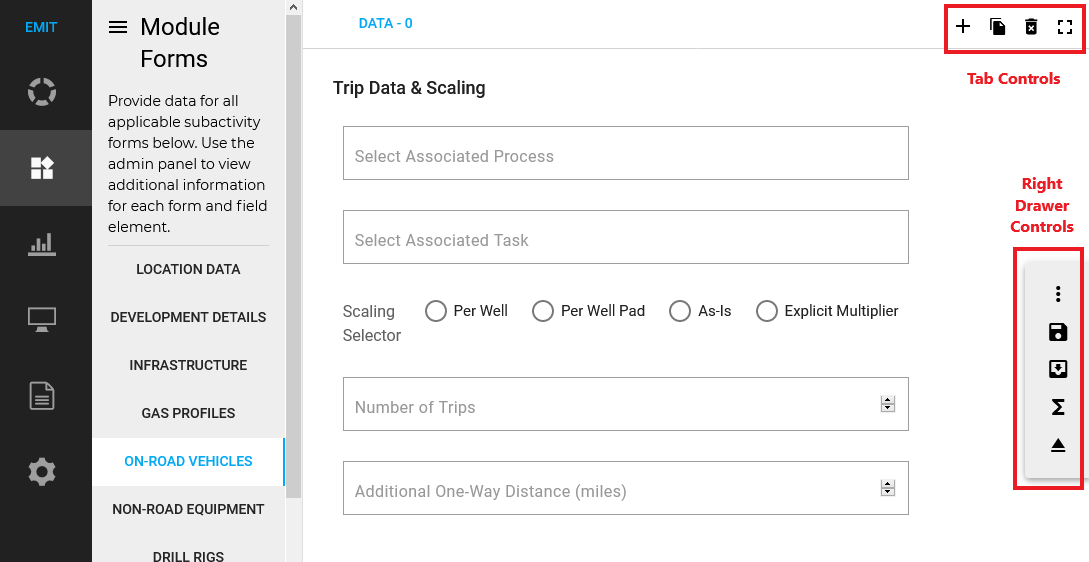
Data for some of the module forms are rendered in EMIT as 'array' types, meaning that users can enter multiple sets of data on these module forms to fully characterize or describe describe the activity or process. For example, the On-Road Vehicles Module Form allows only one vehicle class to be selected. If a project includes activity from both heavy-duty diesel trucks and light duty gasoline vehicles, then the user would define the activity for each of these vehicle types on a separate tab. Note that not all module forms support multiple tabs. For the module forms that do support multiple tabs, the upper right corner of the main screen includes tab controls, as shown in Figure 2. Labels for each tab are listed on the top left of the data entry screen, with the active tab in blue font.

The actions associated with clicking on each of these tab control icons is described below.

  •    Add: Clicking on the Add control provides a new blank module form for data entry by the user. A new tab label for the new entry will appear at the right end of the existing tab labels, with no data entered. Click on that tab to enter data.
  •    Copy: This control copies the active tab data to a new tab that is rendered at the right end of the existing tabs. Data from the copied tab will be entered automatically and can be revised by selecting the new tab.
  •    Delete: The Delete control removes the active tab and data from the set of existing tabs. Note that this action cannot be undone.
  •    Full Screen: Clicking on this icon will switch the EMIT model to the full screen. This icon appears in the upper right corner for all modules and routes.

Projects

Creating a Project

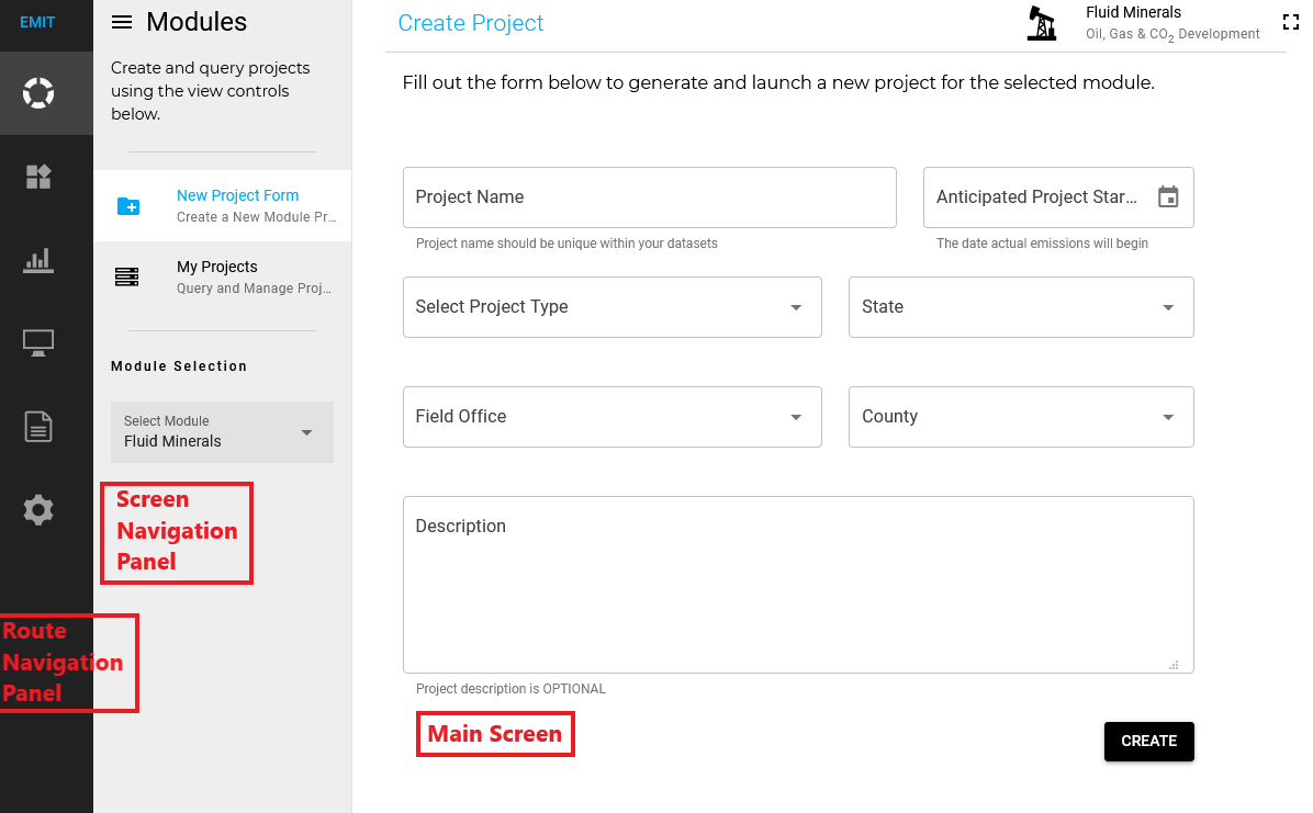
The first step in using EMIT is to create a new project. Projects are created and loaded from the Modules route of EMIT. When EMIT is first opened, the Modules route is shown. To create a new project, the user must select New Project Form from the top of the screen navigation panel as well as the appropriate EMIT module at the bottom of the screen navigation panel from the Module Selection dropdown menu, which includes the following eight modules:

  • Fluid Minerals: Oil, Gas, and CO2 Development
  • Solid Minerals: Coal, Locatable, and Saleable Mineral Mining
  • Forestry: Timber and Wood Products
  • Grazing: Cattle, Sheep, Bison, and Horse Allotments
  • Travel Management: Route and OHV Management
  • Right of Ways: Access, Power, and Pipeline Emissions
  • Vegetation Management: Prescribed Fire, Mechanical, and Chemical Treatments
  • Renewable Energy: Wind and Solar Power Development

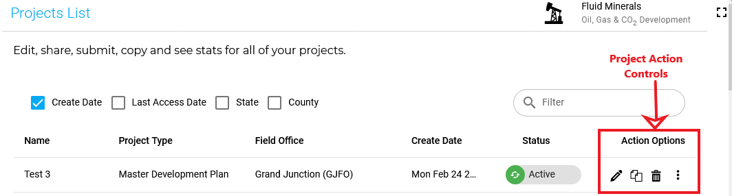
Once a project has been created in the EMIT Tool, it must be loaded before project parameters can be entered and emissions calculated for the project. From the Modules route, select My Projects in the navigation screen. All existing projects of the selected module type for the user will be listed in the main screen. Available project actions are described in the Project Actions section. Data for a loaded project can be entered by selecting the Module Forms route in EMIT.

In the main screen, the user then enters information pertinent to the project to be modeled. All fields other than Description must be populated for a new project to be created. Filling in the Description field is optional, but strongly recommended, particularly if the project information and emissions will be submitted to BLM. The fields included in this menu are shown below.

Parameter Name Type Required or Optional
Project Name String Required
Anticipated Project Start Date Calendar Required
Select Project Type Drop Down Menu Required
Select a State Drop Down Menu Required
Select Field Office Drop Down Menu Required
Select County Drop Down Menu Required
Description String Optional

Once all fields are populated accordingly, the user must click the CREATE button in the bottom right corner of the tool. If the project has been successfully created, a success message will briefly appear at the top of the screen (SUCCESS: Project Created). If no other project is currently loaded, the user will automatically be taken to the Module Forms route tab.

Quick Start: Developing an Example Project

The steps needed to model a hypothetical simple project in EMIT that involves only travel by on-road vehicles are shown below.

  • After logging in to EMIT, create a new project by clicking on CREATE PROJECT at the top right of page in EMIT

    a. Need to fill in all items except Description

    b. Click CREATE button

    c. In PROJECT LIST, click (pencil icon) to load project with the name that was just created

  • The Module Forms page will open. In Module Forms

    a. On LOCATION DATA form, enter data for the following fields:

    • Primary Road Average Commute (miles)
    • Secondary Road Average Commute (miles)
    • Percent of Primary and Secondary Road Lengths Paved (%)
    • Soil Silt Content (%)
    • Soil Moisture Content (%)
    • Days with Precipitation > 0.1 Inch
    • Click on CALCULATIONS button at bottom of form

    b. On INFRASTRUCTURE form, if any industrial roads, enter data for the following fields:

    • Road Length (ft)
    • Road Width (ft)
    • These roads are assumed to be unpaved.
    • Click on CALCULATIONS button at bottom of form

    c. On ON-ROAD VEHICLES form, enter data for the following fields:

    • Optionally, if trip data are broken out by process and task, select appropriate data for these from the dropdown psts in the fields Select Associated Process and Select Associated Task
    • Applicable Scaling Selector (if Explicit Multiplier selected, also enter Multiplier). A scaling selector must be selected to get an emission calculation in terms of tons/project
    • Number of Trips
    • Optionally, Additional One-Way Distance (miles) can be entered if this process/task/vehicle class combination of vehicles travels additional mileage beyond that entered in the LOCATION DATA module, but note that this mileage is assumed to be on paved roads
    • Select Vehicle Class
    • Average Class Weight (tons)
    • Average Class Speed (mph)
    • Click on CALCULATIONS button at bottom of form
    • Repeat the above seven steps under 2) c. to enter data for each unique combination of process, task, and vehicle class by first clicking the + icon in the upper right corner of the form, and then clicking on the new tab created to enter data for the next process/task/vehicle class combination
    • Click on CALCULATIONS button at bottom of form

  • Click more_vert at bottom of Form, then click save icon
  • Go to EMISSIONS module and select the type of output and pollutants desired

  • Module Forms

    Navigating the Module Forms Screens

    The Module Forms route provides the data screens where the user enters the specific data that define their project. The Module Forms specific to the selected Module are listed in the screen navigation panel. Clicking on the name of any of these Module Forms takes the user to that portion of the input. Each Module Form contains the entries for the user to input the data needed to identify and calculate emissions for a related group of activities or equipment.

    Users can explore the Module Forms associated with each loaded module by clicking on the specific list item in the Module Forms route of EMIT. These forms should be completed in order from top to bottom. The activities in the various forms build upon each other and users may experience unexpected results if certain form data are missing from a previous form in the list (for example, emissions calculations may not return a valid result).

    After completing data entry on any of the module forms, the user can click on the calculations icon in the Right Drawer Controls, as shown in Figure 3, to verify that all of the necessary data needed to make emissions calculations for that particular sub-activity / equipment type have been entered. The parameters and values listed when the calculations icon is clicked reflect either user-entered data or a calculated value that EMIT has generated based on the entered data. These intermediate parameters are generally need for one or more emissions calculations in EMIT. EMIT provides the user with parameter dependency information for all the displayed calculated values and informs a user of which data inputs need to have entered in order for that variable to be properly calculated by EMIT. When the user clicks on one of the calculated parameters shown, EMIT will display a list of required inputs and indicates which Module Forms those inputs are entered on. A red X in front of the input indicates that the user has not entered valid data for that input, while a green check mark indicates that the input has a valid entry.

    USER NOTE: It is possible that a user will not want to make all of the possible calculations for a particular activity / equipment type. For example, a user is using EMIT to calculate emissions for drilling a new oil and gas well during the summer months and does not want to include boiler emissions. Leaving the drill rig boiler related input blank on the input form for drill rigs will cause some of the input variables to have red X (when the user hits the calculations icon). This does not mean that emissions for the drill rig engines will not be calculated, it just means that boiler emissions will not be included.

    Fluid Mineral Module Forms

    Use this module to estimate emissions from oil, gas, and carbon dioxide (CO2) mineral development. This module estimates emissions from both construction and production related activities and provides delineation for fee/fed wells (where only a portion of the production is from federal mineral estate). Of all the emissions modules in EMIT, this one has by far the most required user inputs simply due to the complex nature of the industry.

    Project information and data needed to calculate emissions for fluid minerals projects should be entered in the following EMIT Module Forms:

    • LOCATION DATA: Use the Location Data form to capture localized attributes specific to your project area, including climate, surface characteristics, and access routes.

    • DEVELOPMENT DETAILS: Use the Development Details form to capture specific development attributes of you project.

    • INFRASTRUCTURE: Use the Infrastructure form to record basic infrastructure data at project development site(s). Data should include information on well pads, access roads, and pipelines. Create as many entries as required for your project.

    • GAS PROFILES: Use the Gas Profiles form to record gas profile / speciation data, create as many as required for your project.

    • ON-ROAD VEHICLES: Use the On-Road Vehicles form to capture highway traffic, including worker trips, deliveries of materials and equipment, production hauling, and general travel. Emissions estimates for onroad vehicles include combustion exhaust and fugitive dust from roadway surfaces.

    • NON-ROAD EQUIPMENT: Use the Non-Road Equipment form to capture engine data used in a wide range of applications, including heavy equipment, recreational vehicles, locomotives, aircraft, and small equipment and tools.

    • DRILL RIGS: Use the Drill Rigs form to capture specific drill rig data for your project. In general, drill rigs are scaled on a per well basis. However, the form does provide a well service count parameter to allow users to specify a varying degree of use.

    • COMPLETIONS: Use the Completions form to capture project specific data regarding well completions.

    • TANKS: Use the Tanks form to capture specific tank and tank battery data. Enter as many tank design parameters as necessary to accurately reflect project attributes.

    • FIELD GAS PROCESSING: Use the Field Gas Processing form to capture specific data for field gas processing units, including dehydrators and sour gas amine treaters. Flow controllers and process heaters should be specified elsewhere.

    • PROCESS HEATERS: Use the Process Heaters form to capture specific heater data.

    • COMPONENTS: Use the Components form to capture specific component data.

    • PNEUMATIC DEVICES: Use the Pneumatic Devices form to capture specific pneumatics data. Alternatively, if all pneumatic devices are zero bleed or are driven by instrument air, you may elect to remove this form from the data collection process.

    • STATIONARY ENGINES: Use the Stationary Engines form to capture specific engine data.

    • PRODUCTION OPERATIONS: Use the Production Operations form to capture specific operational events that could produce emissions from venting that are not captured elsewhere, specifically for well blowdowns and workovers.

    This module uses the following emission calculation packages:

    Solid Minerals

    Forestry

    Grazing

    Travel Management

    Right of Ways

    Vegetation Management

    Renewable Energy


    Emissions

    Once project data has been entered on the module forms for a project, the resulting emissions as calculated by EMIT are presented in the main screen. When the Emissions module is selected, the screen navigation panel provides several view selectors for reviewing project emissions associated with the loaded project. The user can select between three configurations for viewing emissions results: Table, Pie Chart, or Line Chart. Additionally, on the screen navigation panel, the user can choose to view emissions from either all criteria and hazardous pollutants (PM10, PM2,5, VOC, NOx, CO, SO2, and HAPs) or from greenhouse gases (CO2, CH4, N2O, and CO2e), by clicking the button in front of one of these options. Finally, the screen navigation panel provides a checkbox for selecting to display only Federal emissions (i.e., just the portion of emissions associated with Federal minerals, as identified on the Development Details module form in the Percent Federal Mineral data entry).

    Emissions can be displayed in one of three ways:

    • Table: Selecting Table in the Emissions pane brings up a comprehensive and detailed tabular display of emissions as calculated by EMIT using the data entered for the loaded project. Emissions are itemized by activity, including all emission-generating activity for which emissions could be calculated based on the data included on the module forms. The Description column of the emissions table identifies the activity for which emissions have been calculated. The user may notice that the same activity may be listed several times in the Description column. This happens because the emissions are expressed in different metrics. It is important to consider the corresponding entry in the Units column of the emissions table to understand what each row of emissions data represents. For example, the same activity may have emissions expressed as tons/project, tons/yr, tons/well, etc. The Units column is followed by the columns of emissions for each pollutant, based on the selection made in the Emissions pane (either Criteria & Hazardous Pollutants or Greenhouse Gases).

    • It is also important to note that module forms with data entered on multiple tabs with the same name will appear with identical activity names in the Description column and units in the Units columns, but with different emissions, assuming different data were entered on the different tabs. As an example, on the On-Road Vehicles module form, the user could add multiple tabs for a given task (e.g., daily site visits), with each tab representing emissions from a different vehicle class. In this case, the emissions table would list the activity “On-Road Fugitive Dust – Public Dirt Roads – Daily Site Visits” twice for both sets of units (tons/entry and tons/project). In this case, the entries are shown in the same order as the tabs on the module form that characterizes the activity (i.e., starting with the activity on the leftmost tab and then continuing with each tab moving to the right).

    • Three actions are available within the table view:

      • Sorting Data: All of the pollutant fields and the Units field are sortable by clicking on the column name.

      • Filtering Data: The upper right corner of the Table View screen includes a search bar for filtering emission results. This enables the user to focus on viewing emissions associated with a specific activity or set of units. For example, by entering “tons/project” in the search bar, the emission results would show just the total project emissions for each activity

      • Exporting Data: The entire emissions data table can be exported to a CSV file by clicking on the export icon in the top right corner of the table view, and then selecting whether to open or save the file as named. (The export file name is based on the project name.) Note that any filtering or sorting currently in effect in the table view does not impact the exported data. All data rows associated with the selected project are exported.

    • Pie Chart: Selecting Pie Chart in the Emissions pane will result in the display of a pie chart that shows the compositions of the total project emissions by pollutant for the selected set of pollutants (either Criteria & Hazardous Pollutants or Greenhouse Gases). Clicking on any of the pie wedges will bring up a pie chart showing the contribution of each activity to the total emissions of that pollutant. In either the pie chart of emissions by pollutant or the emissions of activities within a pollutant, hovering over the pie wedge will show the emissions from that wedge.

    • Line Chart: [TBD, under construction]

    Modeling

    By selecting the Modeling icon from the route navigation panel, the user is provided with tools for developing input files for dispersion modeling. Four selections can be made from the Modeling screen navigation panel.

    Project Map:

    • Selecting Project Map from the Modeling screen navigation panel brings up a map of the United States. The user can then zoom in to the project location and then click on the appropriate point of the map to indicate the site of an emissions source or an emissions receptor. EMIT will then add a pin to the map at this point.

    • Clicking on the pin then opens a Map Model Tools panel on the right side of the screen. Here, the user can select either Source or Receptor from the Marker Type drop-down menu.

    • If Source is selected, the user can then define the source parameters: source ID and source type. Finally, the user can enter the emission rate of the source in terms of grams per second. Alternatively, by clicking on the IMPORT EMISSIONS button at the bottom of this panel, EMIT will bring up another menu detailing the sources from the currently loaded project. The user can then check one or more of these sources and then click IMPORT at the bottom right of this menu. EMIT will then automatically pull in the emission rates calculated for the selected equipment.

    • If Receptor is selected from the Marker Type drop-down menu, the user is then able to enter an ID, the elevation, and the height above ground of the receptor.

    • This process can be repeated for multiple receptors and sources.

    Ambient Backgrounds:

    • Selecting Ambient Backgrounds from the Modeling screen navigation panel brings up a screen for entering background ambient pollutant concentrations of PM10, PM2.5, CO, NO2, and SO2. Note that the units expected for each pollutant depend upon the averaging period.

    Model Settings:

    • The main screen provides the user with the ability to select and set the dispersion model options when Model Settings is selected on the screen navigation panel. This includes data on the basic run data, model settings, meteorology and surface settions, source options, and receptor and terrain processing. Note that sources and receptors that are defined on the Project Map screen are available for selection in the Source Options and the Receptor & Terrain Processing menus, respectively.

    Input Preview:

    • Selecting Input Preview from the Modeling screen navigation panel displays the code, generated by EMIT, to be used as input to a dispersion model, based on the information provided by the user.


    Reports

    The Reports screen navigation panel provides the user with access to two different types of automated reports for summarizing the project data. The first includes module fields and project data reports, which provide the user with summary information about the project data needed for EMIT or entered by the user in EMIT. The second includes general conformity reports which evaluate the resulting project emissions in comparison to general conformity requirements. Both of these report types are discussed below.

    Module Fields & Project Data:

    • The reports that can be generated via the Module Fields & Project Data selection from the screen navigation panel are designed to provide users with a detailed look at all the module forms and fields associated with the selected EMIT module. This report can then be distributed among the various parties associated with the project to get an understanding of the data needs for EMIT and to begin gathering the required data on the various activities associated with the project. In order to generate this report, the user must select the desired module on the drop-down menu in the Reports screen navigation panel. Once a module is selected, a RUN REPORT button will appear below the selected module. Clicking on this button will generate the selected report. There is a PRINT button at the top right of the screen. By clicking this button, a print dialog box will open, and the user can make the desired selections to print the report.

    • By checking the Include Project Data box at the bottom of the Reports screen navigation panel, the generated report provides a listing of all the data fields included in the module forms with the user-entered values for the currently loaded project and selected module. This report is a particularly useful tool for enabling all involved project members to review the data entered in EMIT without the need for everyone to use the tool itself. Once the user clicks the RUN REPORT button, report header information will appear including the module and project name. This project name is the currently active project in EMIT. If this report is desired for a different project, the user should close the existing project, return to the Modules screen navigation panel, and load the desired project from the list of projects. The preview of the Project Data report that is generated by clicking the RUN REPORT button will be populated with all the module form fields and the entered values. For module forms with multiple tabs, the values for each tab are displayed in sequential columns with a generic header (e.g., Value 0, Value 1, Value 2, etc.). Clicking on the PRINT button at the top right of the screen opens a print dialog box where the user can make the desired selections to print the report.
    General Conformity:
    • The general conformity reports screen includes two dropdown menus—one to select the NAAQS designation status of the project area and one to select the relevant pollutant that the designation applies to. The options for designation include: Maintenance; Maintenance – Ozone Transport Region; NAA Moderate or Marginal; NAA Moderate or Marginal – Ozone Transport Region; NAA Serious; NAA Severe; and NAA Extreme. The available selections for pollutant are: PM10, PM2.5, CO, NO2, SO2, and Ozone. Once a selection has been made for both the designation and pollutant, click on the ADD POLLUTANT button. Multiple combinations can be selected in this same manner. Once all applicable combinations of NAAQS designation and pollutant have been made, the user must click the RUN REPORT button at the top right of the main screen and the report will be generated on the screen. If the checkbox for Show Extended Report (located at the bottom of the Reports screen navigation panel) is not checked, the report summarizes the general conformity requirements, indicates whether the general conformity requirements do or do not apply for the selected project, and finally displays for each pollutant and designation combination the de minimis emissions total of the pollutant needed for general conformity to apply, the project’s total emissions of the pollutant, and whether emissions from the pollutant pass or fail the general conformity screening check. If the Extended Report option has been selected, the report also lists the total project emissions of each of the selected pollutants, summarized by activity. As with the other reports, there is a PRINT button at the top right of the screen to allow the user to print the report.


    Emission Calculations

    This section provides details on the emission calculations within EMIT. Variables that are entered by the user are noted, along with the corresponding module and data field where the variable should be entered.

    Scalars

    In order to estimate emissions for the entire duration and scope of the project, a number of modules include an entry for the user to indicate whether provided data should be scaled. This entry appears as follows:

    The following module forms include this scaling selector:

    • ON-ROAD VEHICLES
    • NON-ROAD EQUIPMENT
    • FIELD GAS PROCESSING
    • PROCESS HEATERS
    • COMPONENTS
    • PNEUMATIC DEVICES
    • STATIONARY ENGINES

    The user must select one of the scaling selector options, or emissions that are calculated with this scalar will not be calculated. The resulting scalar is determined as follows, based on the user’s selection:

    • As-Is: The scalar used is 1, so emissions are unaffected. This should be considered the default if the user has no additional information for applying a scalar to the entries in the corresponding module form.
    • Explicit Multiplier: When “Explicit Multiplier” is selected, EMIT adds a Multiplier entry in the corresponding module form. The user-supplied input for this Multiplier will be used as the scalar. If this entry is left blank, EMIT will not calculate emissions associated with the corresponding module’s entries on that input tab.
    • Per Well Pad:The data needed for EMIT to calculate the scalar when Per Well Pad is the selected option is entered on the INTRASTRUCTURE module form. The INTRASTRUCTURE module form asks “Scale this entry to represent multiple well pads, access roads and pipelines?” If the box in front of this question is checked, a Multiplier entry appears. The user input for this Multiplier entry is then used as the scalar if “Per Well Pad” is the chosen as the scaling selector option. If the box is not checked, then the scalar is set to 1.
    • Per Well: The data needed for EMIT to calculate the scalar when “Per Well” is the selected option is entered on the INTRASTRUCTURE module form. The entry for Number of Wells per Pad is multiplied by the number of pads to obtain the “Per Well” scalar, both of which are obtained from the INTRASTRUCTURE module form. The number of pads is the multiplier entered by the user in the Multiplier entry that appears if the box in front of “Scale this entry to represent multiple well pads, access roads and pipelines?” is checked. If this box is not checked, the Multiplier defaults to 1.

    Fugitive Dust - Unpaved Road Commuting Operations

    This section describes how EMIT estimates fugitive dust emissions from traffic on unpaved public and industrial roads. The calculations are for particulate matter emissions only and do not include the associated tailpipe emissions from vehicle fuel combustion which are calculated separately as documented in the On-Road Vehicle Exhaust and Evaporative Emissions section. The emission calculations are based on the methodologies outlined in EPA AP-42, Volume I, Chapter 13.2.2. As vehicles travel on unpaved surfaces, particles are created (via pulverization), lifted and dropped by the wheels. These particles can become entrained in the vehicle's turbulent wake as it passes and can then be transported to varying degrees away from the point of origin.

    Fugitive dust emissions factors are estimated via engineering equations (developed from empirical data analysis) for each specific pollutant being analyzed (PM10 and PM2.5). Emission factors for fugitive road dust for travel on public roads are calculated using Equation 1 and emission factors for fugitive dust from travel on industrial roads are calculated using Equation 2.


    Equation 1 - Public Road Fugitive Dust Emissions Factor
    EF = ( k × ( s 12 ) a × ( S 30 ) d ( M 0.5 ) c - C ) × ( 1 - P 365 )

    Where:

    EF = Emission Factor (lb/VMT)
    Parameter PM2.5 PM10
    k (lb/VMT) 0.18 1.8
    a 1 1
    c 0.2 0.2
    d 0.5 0.5
    Source: AP-42, Volume 1, Chapter 13.2.2, Table 13.2.2-2.

    LOCATION DATA—Soil Silt Content (%)

    Silt content of dirt roads (average). Values can vary considerably with geographic location. The silt content of the parent soil in the area can be used however, tests show that road silt content is normally lower than in the surrounding soils because fines are continually removed by the vehicle traffic leaving a higher percentage of coarse particles, see Appendix Table A-1 for typical values.

    • Range: 1.8 - 35
    • Default: 11
    S = Mean Vehicle Speed (mph) calculated in Equation 3

    LOCATION DATA—Soil Moisture Content (%)

    Soil moisture can vary considerably with geographic location and seasonally in any one place. No references are available for this term (the suggested default value is based on the midpoint of the range).

    • Range: 0.03 - 13
    • Default: 6.5
    • PM10 = 0.00047
    • PM2.5 = 0.00036
    Source: AP-42, Volume 1, Chapter 13.2.2, Table 13.2.2-4.

    LOCATION DATA—Days with Precipitation >0.01 inch

    Area Precipitation can vary considerably with geographic location and seasonally in any one place. See Appendix Table A-2 for typical values (the suggested default value is based on the lowest reference value).

    • Range: 0-270
    • Default: 40


    Equation 2 - Industrial Road Fugitive Dust Emissions Factor
    EF = k × ( s 12 ) a × ( W 3 ) b × ( 1 - P 365 )

    Where:

    EF = Emission Factor (lb/VMT)
    Parameter PM2.5 PM10
    k (lb/VMT) 0.15 1.5
    a 0.9 0.9
    b 0.45 0.45
    Source: AP-42, Volume 1, Chapter 13.2.2, Table 13.2.2-2.

    LOCATION DATA—Soil Silt Content (%)

    Silt content of dirt roads (average). Values can vary considerably with geographic location. The silt content of the parent soil in the area can be used however, tests show that road silt content is normally lower than in the surrounding soils because fines are continually removed by the vehicle traffic leaving a higher percentage of coarse particles, See Appendix Table A-1 for typical values.

    • Range: 1.8 - 35
    • Default: 11
    W = Mean Vehicle Weight (tons) calculated in Equation 3

    LOCATION DATA—Days with Precipitation >0.01 inch

    Area Precipitation can vary considerably with geographic location and seasonally in any one place. See Appendix Table A-2 for typical values (the suggested default value is based on the lowest reference value).

    • Range: 0-270
    • Default: 40

    The mean vehicle speed (S) and weight (W) used in Equation 1 and Equation 2 above are determined for the overall fleet due to how the EFs are calculated (i.e. for all vehicles travelling the route, vs. the individual classes of vehicles). Equation 3 shows how the weighted average is calculated for all the vehicle classes listed for the project, where the weighting is based on the total number of trips each vehicle class makes.


    Equation 3 - Weighted Fleet Mean Vehicle Parameters

    W p = i = 1 n p i × t i T t

    Where:

    Wp = Weighted Parameter (either S or W);
    n = Number of Vehicle Classes;

    ON-ROAD VEHICLES—Average Class Weight (tons)

    • Range: 2 – 42

    ON-ROAD VEHICLES—Average Class Speed (mph)

    • Range: 10 - 55
    • Default: 24.5

    ON-ROAD VEHICLES—Number of Trips

    Provide the total trip count for the selected task, where the task identifier is a dropdown control used to speciate vehicle purposes for the project. Any number of tasks and vehicle classes can be entered on separated tabs of the ON-ROAD VEHICLES module form to adequately describe the project's fleet needs and purpose.

    This is the sum of the total number of class trips over all entered tasks and vehicle classes from all tabs entered in the ON-ROAD VEHICLES module.


    Vehicle Miles Traveled (VMT) is calculated in EMIT, using Equation 4, by collecting location specific access data, specifically the primary and secondary routes (and their associated lengths) proponents would use to travel to the project site. These lengths are then scaled in accordance with the percentage of the road lengths that are dirt. Any roads (access, spur, or otherwise) developed as part of the project are assumed to be dirt, and are added to the calculated length. The round trip length is then calculated and this is multiplied by the total number of trips (per vehicle class).


    Equation 4 - Vehicle Miles Traveled (dirt)
    V M T = { [ ( L p + L s ) × Pct Dirt ] + L a } × 2 × T

    Where:

    VMT = Vehicle Miles Traveled (miles/class);

    LOCATION DATAPrimary Road Average Commute (miles)

    LOCATION DATASecondary Road Average Commute (miles)

    LOCATION DATA-Percent of Primary and Secondary Road Lengths Paved (%)

    INFRASTRUCTURE-Road Length (ft)/5,280 (ft/mile)

    Assumptions: Always assumed to be dirt construction.

    ON-ROAD VEHICLES-Number of Trips


    The general equation for calculating unpaved road fugitive dust is shown below in Equation 5. EMIT applies this calculation to each vehicle class provided by the user (to provide task / temporal speciation) and the individual results are then summed to calculate the total unpaved road fugitive dust emissions for the project.


    Equation 5 - Unpaved Road Fugitive Dust Emissions
    E = EF × VMT × ( 1ton 2,000lbs ) × ( 1 - CE 100 )

    Where:

    E = Fugitive Emissions from Vehicles (tons by class)
    EF = Emission Factor (lb/VMT), see equations 1 & 2
    VMT = Vehicle Miles Traveled, see Equation 3

    LOCATION DATA—Dust Control Efficiency (%)
    The dust control efficiency from the application of water, dust pallative, compaction, etc. for pad disturbance and construction activities at the project site(s).


    Fugitive Dust – Heavy Construction Operations


    This section describes how EMIT estimates general heavy construction emissions due to earthwork for a construction project. This includes fugitive dust particulate matter emissions only and does not include tailpipe emissions from fuel combustion, which are calculated separately. Emission calculations for heavy equipment construction operations are based on AP-42, Volume I, Chapter 13.2.3 and 13.2.4 methodology. Chapter 13.2.3 provides the base emission factor used for the fugitive dust from heavy construction operations in terms of total suspended particulate (TSP) while Chapter 13.2.4 provides the particle size multipliers that are used to convert the TSP emission factor to PM10 and PM2.5 emission factors.

    Potential emissions associated with fugitive dust generated from land disturbance and associated wind erosion are based on an engineering calculation using emissions factors for heavy construction and user input to quantify the amount of land area disturbed by these operations and the duration of the disturbance. Fugitive dust emissions associated with heavy construction operations at a well pad include land disturbances that occur in creating the pad, building access roads where needed, and laying pipeline where appropriate. Emissions are calculated using Equation 6

    Equation 6 – Fugitive Dust Emissions from Heavy Construction Operations (tons/well pad)
    E PM = A d × EF × k × N d × 1 month 30 days × 0.667 × ( 1 - CntrlEff 100 )

    Where:

    EPM = Particulate Matter Fugitive Dust Emissions for Selected Particle Size (tons/well pad)
    Ad = Total Disturbed Area (acres)

    TSP emission factor (EF) is equal to 1.2 ton/acre-month based on AP-42, Volume I, Section 13.2.3

    For PM10, k=0.35.
    For PM2.5, k=0.053.
    Particle size multipliers for PM10 and PM2.5, relative to TSP, are from AP-42, Volume I, Section 13.2.4

    INFRASTRUCTURE – Days to Complete All Earth Moving Activities
    The total number of days until initial soil stabilization occurs for all entry activities (i.e. heavy earthwork ceases).

    LOCATION DATA – Dust Control Efficiency (%)
    The dust control efficiency from the application of water, dust palliative, compaction, etc. for pad disturbance and construction activities at the project site(s).


    The total disturbed area (Ad) in Equation 6 is the sum of the disturbance area for each well pad, the disturbance for the access road needed for each well pad, and the disturbance area needed for pipeline construction associated with each well pad. This calculation is shown in Equation 7.


    Equation 7 – Total Disturbed Area from Heavy Construction Operations (acres/year)
    A d = ( AcresInit + ( AccLen × AccWd ) + ( PipeLen × 50ft ) 43,560sqft per acre ) × NumPads

    Where:

    Ad = Total Disturbed Area (acres)

    INFRASTRUCTURE – Well Pad Construction: Total Disturbance Area (acres)
    The average initial land disturbance area for the well pad (per well pad if scaled).

    INFRASTRUCTURE– Access Road Construction: Road Length (ft)
    The length of the disturbance area associated with an access road spur construction (feet). For a multiple pad entry, provide the average length.

    INFRASTRUCTURE – Access Road Construction: Road Width (ft)
    The width of the disturbance area associated with an access road spur construction (feet). For a multiple pad entry, provide the average width.

    INFRASTRUCTURE – Pipeline Construction: Disturbance Length (ft)
    The length of the disturbance area associated with pipeline construction (feet). For a multiple pad entry, provide the average length. The equation above assumes a 50-foot right-of-way for all pipeline disturbances.

    INFRASTRUCTURE – Multiplier
    This multiplier can be used to estimate emissions for multiple pads when project specific data is unknown, or pad development is expected to be the same on each pad. If the checkbox next to “Scale this entry to represent multiple well pads, access roads, and pipelines?” is not checked, EMIT will use a value of 1.


    EMIT also calculates the rate of fugitive dust emissions from heavy construction operations in units of pounds per hour. These are calculated in Equation 8 for dust from well pad operations, Equation 9 for dust from access road operations, and Equation 10 for dust from pipeline operations.


    Equation 8 – Rate of Fugitive Dust Emissions from Well Pad Operations (lb/hr)
    ER PM = AcresInit × EF × k × 1 month 30 days × 1 day 12hrs disturbed × 2,000lb ton × ( 1 - CntrlEff 100 )

    Where:

    ERPM = Rate of Particulate Matter Fugitive Dust Emissions for Selected Particle Size from Well Pad Operations (lb/hr)

    INFRASTRUCTURE –Total Disturbance Area (acres)
    The average initial land disturbance area for the well pad (per well pad if scaled).

    TSP emission factor (EF) is equal to 1.2 ton/acre-month based on AP-42, Volume I, Section 13.2.3

    For PM10, k=0.35.
    For PM2.5, k=0.053.
    Particle size multipliers for PM10 and PM2.5, relative to TSP, are from AP-42, Volume I, Section 13.2.4

    LOCATION DATA – Dust Control Efficiency (%)
    The dust control efficiency from the application of water, dust palliative, compaction, etc. for pad disturbance and construction activities at the project site(s).


    Equation 9 – Rate of Fugitive Dust Emissions from Access Road Operations (lb/hr)
    ER PM = ( AccLen × AccWd ) sqft 43,650sqft per acre × EF × k × 1 month 30 days × 1 day 12hrs disturbed × 2,000lb ton × ( 1 - CntrlEff 100 )

    Where:

    ERPM = Rate of Particulate Matter Fugitive Dust Emissions for Selected Particle Size from Access Road Operations (lb/hr)

    INFRASTRUCTURE – Access Road Construction: Road Length (ft)
    The length of the disturbance area associated with an access road spur construction (feet). For a multiple pad entry, provide the average length.

    INFRASTRUCTURE – Access Road Construction: Road Width (ft)
    The width of the disturbance area associated with an access road spur construction (feet). For a multiple pad entry, provide the average width.

    TSP emission factor (EF) is equal to 1.2 ton/acre-month based on AP-42, Volume I, Section 13.2.3

    For PM10, k=0.35.
    For PM2.5, k=0.053.
    Particle size multipliers for PM10 and PM2.5, relative to TSP, are from AP-42, Volume I, Section 13.2.4

    LOCATION DATA – Dust Control Efficiency (%)
    The dust control efficiency from the application of water, dust palliative, compaction, etc. for pad disturbance and construction activities at the project site(s).


    Equation 10 – Rate of Fugitive Dust Emissions from Pipeline Operations (lb/hr)
    ER PM = ( PipeLen × PipeWd ) sqft 43,650sqft per acre × EF × k × 1 month 30 days × 1 day 12hrs disturbed × 2,000lb ton × ( 1 - CntrlEff 100 )

    Where:

    ERPM = Rate of Particulate Matter Fugitive Dust Emissions for Selected Particle Size from Pipeline Operations (lb/hr)

    INFRASTRUCTURE – Pipeline Construction: Disturbance Length (ft)
    The length of the disturbance area associated with pipeline construction (feet). For a multiple pad entry, provide the average length.

    INFRASTRUCTURE – Pipeline Construction: ROW Width (ft)
    The width of the right-of-way associated with the pipeline construction.

    TSP emission factor (EF) is equal to 1.2 ton/acre-month based on AP-42, Volume I, Section 13.2.3

    For PM10, k=0.35.
    For PM2.5, k=0.053.
    Particle size multipliers for PM10 and PM2.5, relative to TSP, are from AP-42, Volume I, Section 13.2.4

    LOCATION DATA – Dust Control Efficiency (%)
    The dust control efficiency from the application of water, dust palliative, compaction, etc. for pad disturbance and construction activities at the project site(s).

    This calculation is used in the following EMIT modules:

    • Fluid Minerals
    • Solid Minerals
    • Grazing
    • Vegetation
    • Forestry
    • Travel
    • Renewable Energy


    On-Road Vehicle Exhaust and Evaporative Emissions


    This section describes how EMIT estimates emissions from on-road vehicle exhaust from the combustion of fuel in on-road reciprocating internal combustion engines as well as vehicle evaporation processes. These emissions are estimated using pre-calculated emission factors obtained by running EPA’s Motor Vehicle Emission Simulator (MOVES2014a) model for a 2018 calendar year multiplied by the corresponding number of vehicle miles traveled (VMT).

    The MOVES model uses inputs on meteorology, vehicle age, vehicle type, vehicle speed, fuel, and road classification to estimate emission factors. The model can be run using site-specific data or at a more regional level using typical information for the county. Given the impracticalities of running MOVES for every single BLM project, MOVES was run using typical county information simulating Roosevelt County, Montana to generate “typical” emission factors. A sensitivity analysis was completed to show that this method is reasonable.

    The emission factors from MOVES used in EMIT account for the following emission sources:

    • Running exhaust
    • Crankcase running exhaust
    • Evaporative fuel leaks
    • Evaporative fuel vapor venting
    • Evaporative permeation
    • Refueling displacement vapor loss
    • Refueling spillage loss

    EMIT provides the ability to model gasoline passenger cars, gasoline or diesel passenger trucks, diesel single unit short-haul trucks, and diesel combination long-haul trucks. (MOVES contains more vehicle classes than those included in EMIT, but BLM determined these are the only vehicle classes that apply to BLM projects.) Emission factors are selected in EMIT from a look-up table based on the vehicle class selected in the Vehicle Data section of the ON-ROAD VEHICLES module form.

    Vehicle miles traveled (VMT) is calculated in EMIT for each unique trip process, task, and vehicle class selected by the user (i.e., for each tab on the ON-ROAD VEHICLES module form with sufficient data entered). VMT is the product of the length of road a vehicle travels and the expected number of trips for that road length. EMIT calculates VMT by collecting location-specific access data, specifically the primary and secondary routes (and their associated lengths) proponents would use to travel to the project site. Any roads (access, spur, or otherwise) developed as part of the project are added to the calculated length. Additional trip lengths, beyond the primary and secondary access routes that the vehicle might travel to the project location to complete or provide resources for the associated task(s) are also included. All of these trip lengths are the one-way road lengths. These road lengths are summed and multiplied by 2 to obtain the total round-trip distance traveled and this round-trip length is then multiplied by the total number of trips (per vehicle class) to estimate the VMT for the vehicle class. Equation 11 shows this calculation.

    Equation 11 – Calculation of Vehicle Miles Traveled
    VMT = ( Lp + Ls + La ) × T × 2

    Where:

    VMT = Vehicle Miles Traveled for the Specified Process, Task, and Vehicle Class (miles)

    LOCATION DATA - Primary Road Average Commute (miles)
    The primary road length represents the average or most representative one-way distance for commutes on primary roads (arterial) to the project area or sites (assumed used by all vehicle classes).

    LOCATION DATA - Secondary Road Average Commute (miles)
    The secondary road length represents the average or most representative one-way distance for commutes on secondary roads (collector) to the project area or sites (assumed used by all vehicle classes).

    ON-ROAD VEHICLES - Additional One-Way Distance (miles)
    The additional road length traveled represents the one-way distance beyond the primary and secondary access route lengths and project-specific roads the vehicle might travel to the project location to complete or provide resources for the associated task(s)

    ON-ROAD VEHICLES - Number of Trips
    The number of total trips represents the total one-way trip count for the selected combination of process, task, and vehicle class (all on the ON-ROAD VEHICLES module form). Any number of process/task/vehicle class combinations can be added by using multiple tabs on the ON-ROAD VEHICLES module form to adequately describe the project's fleet needs and purpose.


    Emissions are calculated in terms of tons per task as shown in Equation 12 for each specified process, task, and vehicle class identified on the ON-ROAD VEHICLES module form. EMIT also calculates total project emissions from on-road vehicle exhaust in terms of tons per project. This result is obtained by multiplying the emissions calculated with Equation 12 by the scalar determined by the Scaling Selector chosen on the ON-ROAD VEHICLES module form.


    Equation 12 – On-Road Vehicle Emissions (tons/task)

    E x = EF x × VMT × 453.59g lb × 2,000lb ton

    Where:

    Ex = Emissions from Selected Process, Task, and On-Road Vehicle Class for Pollutant X (tons)

    EMIT will look up the appropriate emission factor based on the vehicle class selected in the Vehicle Data section of the ON-ROAD VEHICLES module form and the project year, specified on the Project Form. The emission factors were calculated using EPA’s MOVES model for calendar years 2018, 2020, 2022, 2024, and 2030. EMIT will look up the appropriate emission factor using the selected vehicle class and the project start year. EMIT will select the emission factors for the specified vehicle class that are equal to or less than the project year. For example, a project year of 2023 would use emission factors from the MOVES model run for calendar year 2022. The emission factors used by EMIT for on-road vehicles can be found in Table A-3.

    The VMT for the selected process, task, and vehicle class (miles), as calculated in Equation 11.

    It should be noted that the MOVES emission factors do not change with geographical location in EMIT. The sensitivity analysis discussed above shows that this is a reasonable assumption. In addition, all road types for BLM projects are assumed to be “rural” rather than “urban”. This assumption is made because BLM projects do not typically occur in urban areas.

    EMIT only quantifies total HAP, but the MOVES model includes emissions for some individual HAPs. The percentage of total HAP that can be used to estimate individual HAPs can be found in Table A-4.

    This calculation is used in the following EMIT modules:

    • Fluid Minerals
    • Solid Minerals
    • Grazing
    • Vegetation
    • Forestry
    • Travel
    • Renewable Energy


    Non-Road Mobile Equipment – Exhaust and Evaporative Emissions


    This section describes how emissions from exhaust and evaporative processes from non-road equipment are calculated with EMIT. (Fugitive emissions caused by non-road equipment are discussed in other sections.) These emissions are estimated using pre-calculated emission factors obtained by running EPA’s Motor Vehicle Emission Simulator (MOVES2014a) model for a 2018 calendar year.

    This version of MOVES incorporates the NONROAD2008a algorithms for estimating emissions from non-road equipment. This model uses inputs on meteorology, vehicle age, vehicle type, fuel and roads to estimate emission factors. The model can be run using site-specific data or at a more regional level using typical information for the county. Given the impracticalities of running MOVES for every single BLM project, MOVES was run using typical county information to generate “typical” emission factors. A sensitivity analysis analysis was completed to show that this method is reasonable. The emission factors from MOVES account for the following emission processes:

    • Running Exhaust
    • Crankcase Running Exhaust
    • Refueling Displacement Vapor Loss
    • Refueling Spillage
    • Evap Tank Permeation
    • Evap Hose Permeation
    • Diurnal Fuel Vapor Venting
    • HotSoak Fuel Vapor Venting
    • Running Loss Fuel Venting

    The primary inputs for calculating emissions from non-road equipment are entered in EMIT by the user in the NON-ROAD EQUIPMENT module form. On this form, the entries for the process, task, non-road category, and equipment type combine to uniquely define the set of equipment for which emissions are being modeled. The inputs for non-road category and equipment type are used within EMIT to look up the appropriate emission factors. Note that the available equipment types will change based on the selection for the non-road category. For most projects, there will be multiple such combinations needed to account for all of the non-road equipment being used on a project. When using EMIT to calculate emissions from non-road equipment, the user should make a list of all the nonroad equipment pieces that will be needed, categorizing the equipment based on the available menu selections. Each different grouping of equipment should be modeled by adding additional tabs on the NON-ROAD EQUIPMENT module form to appropriately represent each of these groups.

    Equation 13 shows how EMIT calculates emissions for each equipment class. This equation represents the per-task emissions. To obtain the total project emissions for this equipment class, EMIT multiplies the task-level emissions by the appropriate scalar input by the user in EMIT.


    Equation 13 – Non-Road Mobile Equipment Emissions
    E x = EF x × NR_hpHrs × lb 453.59g × ton 2000lb

    Where:

    Ex = Emissions from Specified Non-Road Engine for Pollutant X (ton/project)

    EMIT will look up the appropriate emission factor based on the non-road category and equipment type selected in NON-ROAD EQUIPMENT—Select Non-Road Equipment and Select Equipment Type. The emission factors were calculated using EPA’s MOVES model for a 2018 calendar year. These emission factors for non-road equipment can be found in Table A-5.

    NR_hpHrs = Horsepower-hours (hp-hr), calculated in Equation 14.

    The non-road horsepower-hours (NR_hpHrs) in Equation 13 represent the activity for the specified non-road engine type. Equation 14 illustrates how the non-road hp-hr term is calculated.


    Equation 14 – Calculation of Horsepower-hours for Non-Road Mobile Equipment
    NR_hpHrs = HP × Cnt × ( LF 100 ) × OpDays × OpHrs

    Where:

    NR_hpHrs = Total Horsepower-hours for Selected Non-Road Equipment Type Over the Duration of the Project (hp-hr)

    NON-ROAD EQUIPMENT-Horsepower Rating (bhp)

    The horsepower rating should be specific to the equipment class selected. It is recommended that the user prepare a list of all equipment that will be required for the project and either estimate the horsepower rating or look up equipment types on manufacturer websites to identify specific horsepower ratings. Here are a few potential resources to find horsepower ratings:

    NON-ROAD EQUIPMENT-Equipment Count

    This should represent the number of pieces of equipment of the selected equipment type that will be used on the project.

    NON-ROAD EQUIPMENT-Number of Operating Days

    This should represent the number of days that the specified type of equipment will be used over the course of the project.

    NON-ROAD EQUIPMENT-Operating Hours per Day

    This should represent the average number of hours that all the pieces of equipment of the specified type will be used on a typical day.

    NON-ROAD EQUIPMENT-Average Load Factor

    In most cases, 100% should be used as the default because the MOVES emission factors for the non-road equipment incorporate an averge load factor specific to the equipment type. If however, the load factor for the specific piece of equipment being used is significantly different than the MOVES default for that equipment type, the user should divide the specific load factor for equipment being used in the project by the MOVES default load factor for that equipment type, and multiply by 100.


    Note that the NONROAD module in MOVES does not produce emission factors for CH4 and N2O. Even though emissions of CH4 and N2O are likely negligible compared to CO2, EMIT uses ratios of CH4/CO2 and N2O/CO2 from the MOVES ONROAD model to estimate CH4 and N2O emission factors for NONROAD sources. In addition, the NONROAD module does not produce emission factors for HAP. EMIT uses ratios of HAP/VOC from the MOVES ONROAD model to estimate HAP emission factors for NONROAD sources. The percentage of the total HAP emissions that can be used to estimate individual HAPs can be found in Table A-4.

    This calculation is used in the following EMIT modules:

    • Fluid Minerals
    • Solid Minerals
    • Grazing
    • Vegetation
    • Forestry
    • Travel
    • Renewable Energy


    Drill Rig Emissions


    This section describes how emissions from drill rigs are calculated with EMIT. EMIT enables the calculation of emissions from the primary drill rig engines, auxiliary engines, and associated boilers. All emission factors used in EMIT for drill rigs can be found in Appendix Table A-6.

    The emission factors used to calculate emissions from the primary drill rig diesel engines and auxiliary engines are obtained from 40 CFR, Part 89, “Control of Emissions from New and In-Use Nonroad Compression-Ignition Engines.” When these engines are 2- or 4-stroke natural gas reciprocating internal combustion engines (RICE) fueled by natural gas, the emission factors are based on EPA’s AP-42, Section 3.2, Tables 3.2-1, 3.2-2, and 3.2-3, with the emission units from these tables converted from lb/MMBtu to g/hp-hr. Emission factors for new natural gas engines that are subject to New Source Performance Standards (NSPS) for stationary spark ignition internal combustion engines are obtained from Table 1 of 40 CFR Part 60 ” Standards of Performance for Stationary Spark Ignition Internal Combustion Engines.”

    Emission factors from boilers associated with a drill rig are obtained from EPA’s AP-42, Section 1.4, Tables 1.4-1 and 1.4-2 for natural gas boilers and from AP-42, Section 1.3 for boilers fueled by diesel or propane. The emission factors used in EMIT assume that the boilers are less than 100 MMBtu/hr of heat input and that the fuel contains 15 ppm sulfur, where applicable. All emission factors used in EMIT for drill rigs can be found in Appendix Table A-6.


    Drill Rig Primary Engines

    Drill rig emissions are calculated using the total horsepower-hours of the primary drill rig based on the engine's power rating and the hours the drill rig is operated. This is calculated with Equation 15.


    Equation 15 – Calculation of Horsepower-hours per Well for Primary Drill Rig Engines (hp-hr/well)
    Rig_hpHrs = RigHP × EngCnt × ( LF 100 ) × OpDays × OpHrs

    Where:

    The calculated horsepower hours of the primary drill rig engines on a per well basis.

    DRILL RIGS—Primary Engine Horsepower (bhp)
    The rated horsepower of the primary engines.

    DRILL RIGS—Number of Rig Primary Engines
    The number of primary engines delivering power to the rig (typically 3).

    DRILL RIGS —Primary Engine Load Factor
    The percent of the engine’s maximum horsepower developed and operated at on average over the drilling process.

    DRILL RIGS —Average Days to Drill a Single Project Well
    The number of days (on average) it takes to drill a project well given the formation and over burden geology, total measured depth (TMD) of the well(s), etc.

    DRILL RIGS —Daily Operating Hours (hrs/day)
    The number of hours per day the rig will operate.


    Equation 16 shows how EMIT calculates emissions for drill rig primary engines for the type of rig employed to complete the applicable portion of the drilling / completion / workover schedule, as selected on the DRILL RIGS module form for the Rig Type. This equation represents the total drill rig engine emissions for the selected rig type per well in units of tons per well. To obtain the total project emissions (tons/project) for this drill rig primary engine of the selected Rig Type, EMIT multiplies the emissions calculated using Equation 16 by the number of Project Wells Serviced, as entered on the DRILL RIGS module form. The Project Wells Serviced entry should represent the number of project wells that will be serviced by the rig. If that number is less than the total number of wells, an additional rig of the same type should be provided. For a split entry of the same type, EMIT assumes that the rigs will run simultaneously. EMIT estimates the maximum tons of pollutant per year using Equation 17. EMIT also calculates the rate of emissions from primary drill rig engines in terms of pounds per hour using Equation 18 and in units of grams per second using Equation 19.


    Equation 16 – Drill Rig Primary Engine Emissions for Selected Drill Rig Type (tons/well)
    E x = RigEF x ( g hp hr ) × Rig_hpHrs ( hp hrs well ) × lb 453.59g × ton 2,000lb

    Where:

    Ex= Emissions from the Selected Drill Rig Type for Pollutant x (tons/well)

    EMIT will look up the appropriate auxiliary engine emission factor based on the user’s selections on the DRILL RIGS module form selections for Primary Engine Fuel Type and Primary Engine Tier. The data sources for these emission factors are described at the beginning of this section.

    The horsepower-hours for primary drill rig engine of the selected type are calculated with Equation 15.


    Equation 17 – Drill Rig Primary Engine Emissions for Selected Drill Rig Type (max tons/year)
    E x = RigEF x ( g hp hr ) × Rig_hpHrs ( hp hr well ) × MaxWells × ( OpWells WellsPerPad × PadMult ) × lb 453.59g × ton 2,000lb

    Where:

    Ex= Emissions from the Selected Drill Rig Type for Pollutant x (max tons/yr)

    EMIT will look up the appropriate auxiliary engine emission factor based on the user’s selections on the DRILL RIGS module form selections for Primary Engine Fuel Type and Primary Engine Tier. The data sources for these emission factors are described at the beginning of this section.

    The horsepower-hours for primary drill rig engine of the selected type are calculated with Equation 15.

    DEVELOPMENT DETAILS - Maximum Number of Wells Drilled in Any Project Year

    DRILL RIGS - Number of Project Wells Serviced
    The number of project wells that will be serviced by the rig. When the number is less than the total, an additional rig of the same type should be provided. The assumption for a split entry of the same type is that the rigs will run simultaneously.

    INFRASTRUCTURE - Number of Wells per Pad
    The number of NEW wells that will be drilled from the well pad. Do NOT include any existing wells, as this value can be used to scale various activities within the model. Field is only applicable to well and mixed facility pad types. Provides for spatial allocation for development activities.

    INFRASTRUCTURE- Multiplier
    This is a multiplier that can be used to estimate emissions for multiple pads when project specific data is unknown, or pad development is expected to be the same. In order to access this field for data entry, the user must check the query on the INFRASTRUCTURE module form asking “Scale this entry to represent multiple well pads, access roads and pipelines?” If this box is left unchecked, EMIT sets PadMult to 1.


    Equation 18 – Drill Rig Primary Engine Rate of Emissions for Selected Drill Rig Type (lb/hr)
    E x = RigEF x ( g hp hr ) × Rig_hpHrs ( hp hr well ) ( OpDays × OpHrs ) × lb 453.59g

    Where:

    Ex= Emissions from the Selected Drill Rig Type for Pollutant x (lb/hr)

    EMIT will look up the appropriate auxiliary engine emission factor based on the user’s selections on the DRILL RIGS module form selections for Primary Engine Fuel Type and Primary Engine Tier. The data sources for these emission factors are described at the beginning of this section.

    The horsepower-hours for primary drill rig engine of the selected type are calculated with Equation 15.

    DRILL RIGS —Average Days to Drill a Single Project Well
    The number of days (on average) it takes to drill a project well given the formation and over burden geology, total measured depth (TMD) of the well(s), etc.

    DRILL RIGS —Daily Operating Hours (hrs/day)
    The number of hours per day the rig will operate.


    Equation 19 – Drill Rig Primary Engine Rate of Emissions for Selected Drill Rig Type (g/s)
    E x = RigEF x ( g hp hr ) × Rig_hpHrs ( hp hr well ) ( OpDays × OpHrs ) × hr 3,600s

    Where:

    Ex= Emissions from the Selected Drill Rig Type for Pollutant x (g/s)

    EMIT will look up the appropriate auxiliary engine emission factor based on the user’s selections on the DRILL RIGS module form selections for Primary Engine Fuel Type and Primary Engine Tier. The data sources for these emission factors are described at the beginning of this section.

    The horsepower-hours for primary drill rig engine of the selected type are calculated with Equation 15.

    DRILL RIGS —Average Days to Drill a Single Project Well
    The number of days (on average) it takes to drill a project well given the formation and over burden geology, total measured depth (TMD) of the well(s), etc.

    DRILL RIGS —Daily Operating Hours (hrs/day)
    The number of hours per day the rig will operate.


    Auxiliary Engines on Drill Rig Platform

    Auxiliary engine emissions are calculated using the total horsepower-hours of operation for the auxiliary engines. This is calculated with Equation 20.


    Equation 20 – Calculation of Horsepower-hours per Well for Auxiliary Engines on Drill Rig Platform (hp-hr/well)
    Aux_hpHrs = AuxHP × AuxCnt × ( AuxLF 100 ) × OpDays × OpHrs

    Where:

    The calculated horsepower hours of the auxiliary engines on the drill rig platform on a per well basis.

    DRILL RIGS—Average Auxiliary Engine Horsepower (bhp)
    The average horsepower of all the auxiliary engines on the rig platform.

    DRILL RIGS—Auxiliary Engine Count
    The number of auxiliary engines on the rig platform.

    DRILL RIGS —Average Auxiliary Engine Load Factor (%)
    The average load factor of all the auxiliary engines on the rig platform.

    DRILL RIGS —Average Days to Drill a Single Project Well
    The number of days (on average) it takes to drill a project well given the formation and over burden geology, total measured depth (TMD) of the well(s), etc.

    DRILL RIGS —Daily Operating Hours (hrs/day)
    The number of hours per day the rig will operate.


    Equation 21 shows how EMIT calculates emissions from auxiliary engines used on drill rig platforms for the type of rig employed and the selected auxiliary engine fuel type and auxiliary engine emissions tier selected on the DRILL RIGS module form. This equation represents the total auxiliary engine emissions for the selected type of auxiliary engine per well in units of tons per well. To obtain the total project emissions (tons/project) for auxiliary engine emissions on the drill rig platform, EMIT multiplies the emissions calculated using Equation 21 by the number of Project Wells Serviced, as entered on the DRILL RIGS module form. The Project Wells Serviced entry should represent the number of project wells that will be serviced by the rig. If that number is less than the total number of wells, an additional rig of the same type should be provided. For a split entry of the same type, EMIT assumes that the rigs will run simultaneously. EMIT estimates the maximum tons of pollutant per year from auxiliary engines with Equation 22. EMIT also calculates the rate of emissions from auxiliary engines in terms of pounds per hour using Equation 23 and in units of grams per second using Equation 24.


    Equation 21 – Emissions from Auxiliary Engines on Drill Rig Platform (tons/well)
    E x = AuxEF x ( g hp hr ) × Aux_hpHrs ( hp hr well ) × lb 435.59g × ton 2,000lb

    Where:

    Ex= Emissions from Auxiliary Engines for Pollutant x (tons/well)

    EMIT will look up the appropriate auxiliary engine emission factor based on the user’s selections on the DRILL RIGS module form selections for Auxiliary Engine Fuel Type and Auxiliary Engine Emissions Tier. The data sources for these emission factors are described at the beginning of this section.

    The calculated horsepower hours of the auxiliary engines on the drill rig platform on a per well basis, as calculated in Equation 20.


    Equation 22 – Emissions from Auxiliary Engines on Drill Rig Platform (max tons/year)
    E x = AuxEF x ( g hp hr ) × Aux_hpHrs ( hp_hr well ) × MaxWells × ( OpWells WellsPerPad × PadMult ) × lb 453.59g × ton 2,000lb

    Where:

    Ex= Emissions from Auxiliary Engines for Pollutant x (max tons/yr)

    EMIT will look up the appropriate auxiliary engine emission factor based on the user’s selections on the DRILL RIGS module form selections for Auxiliary Engine Fuel Type and Auxiliary Engine Emissions Tier. The data sources for these emission factors are described at the beginning of this section.

    The calculated horsepower hours of the auxiliary engines on the drill rig platform on a per well basis, as calculated in Equation 20.

    DEVELOPMENT DETAILS - Maximum Number of Wells Drilled in Any Project Year

    DRILL RIGS - Number of Project Wells Serviced
    The number of project wells that will be serviced by the rig. When the number is less than the total, an additional rig of the same type should be provided. The assumption for a split entry of the same type is that the rigs will run simultaneously.

    INFRASTRUCTURE - Number of Wells per Pad
    The number of NEW wells that will be drilled from the well pad. Do NOT include any existing wells, as this value can be used to scale various activities within the model. Field is only applicable to well and mixed facility pad types. Provides for spatial allocation for development activities.

    INFRASTRUCTURE - Multiplier
    This is a multiplier that can be used to estimate emissions for multiple pads when project specific data is unknown, or pad development is expected to be the same. In order to access this field for data entry, the user must check the query on the INFRASTRUCTURE module form asking “Scale this entry to represent multiple well pads, access roads and pipelines?” If this box is left unchecked, EMIT sets PadMult to 1.


    Equation 23 – Rate of Emissions from Auxiliary Engines on Drill Rig Platform (lb/hr)
    E x = AuxEF x ( g hp hr ) × Aux_hpHrs ( hp hr well ) ( OpDays × OpHrs ) × lb 453.59g

    Where:

    Ex= Rate of Emissions from Auxiliary Engines for Pollutant x (lb/hr)

    EMIT will look up the appropriate auxiliary engine emission factor based on the user’s selections on the DRILL RIGS module form selections for Auxiliary Engine Fuel Type and Auxiliary Engine Emissions Tier. The data sources for these emission factors are described at the beginning of this section.

    The calculated horsepower hours of the auxiliary engines on the drill rig platform on a per well basis, as calculated in Equation 20.

    DRILL RIGS —Average Days to Drill a Single Project Well
    The number of days (on average) it takes to drill a project well given the formation and over burden geology, total measured depth (TMD) of the well(s), etc.

    DRILL RIGS —Daily Operating Hours (hrs/day)
    The number of hours per day the rig will operate.


    Equation 24 – Rate of Emissions from Auxiliary Engines on Drill Rig Platform (g/s)
    E x = AuxEF x ( g hp hr ) × Aux_hpHrs ( hp hr well ) ( OpDays × OpHrs ) × hr 3,600s

    Where:

    Ex= Rate of Emissions from Auxiliary Engines on Drill Rig Platform (g/s)

    EMIT will look up the appropriate auxiliary engine emission factor based on the user’s selections on the DRILL RIGS module form selections for Auxiliary Engine Fuel Type and Auxiliary Engine Emissions Tier. The data sources for these emission factors are described at the beginning of this section.

    The calculated horsepower hours of the auxiliary engines on the drill rig platform on a per well basis, as calculated in Equation 20.

    DRILL RIGS —Average Days to Drill a Single Project Well
    The number of days (on average) it takes to drill a project well given the formation and over burden geology, total measured depth (TMD) of the well(s), etc.

    DRILL RIGS —Daily Operating Hours (hrs/day)
    The number of hours per day the rig will operate.


    Boilers on Drill Rig Platform

    The total boiler heat input used in calculating emissions from boilers on the drill rig platform is calculated with Equation 25.


    Equation 25 – Calculation of Drill Rig Boiler Heat Input (MMBtu/well)
    Blr_HtIn = BlrHt × BlrHrs

    Where:

    The calculated total heat input of the drill rig boiler.

    DRILL RIGS—Boiler Heat Rating (MMBtu/hr)
    The average horsepower of all the auxiliary engines on the rig platform.

    DRILL RIGS —Boiler Annual Operating Hours (hrs/yr)
    The total number of hours the boiler will run while in use for the project.


    Equation 26 shows how EMIT calculates emissions from boilers used on drill rig platforms for the boiler fuel type selected on the DRILL RIGS module form. This equation represents the total boiler emissions for the selected fuel type per well in units of tons per well. To obtain the total project emissions (tons/project) from boilers on the drill rig platform, EMIT multiplies the emissions calculated using Equation 26 by the number of Project Wells Serviced, as entered on the DRILL RIGS module form. The Project Wells Serviced entry should represent the number of project wells that will be serviced by the rig. If that number is less than the total number of wells, an additional rig of the same type should be provided. For a split entry of the same type, EMIT assumes that the rigs will run simultaneously. EMIT estimates the maximum tons of pollutant per year from boilers with Equation 27. EMIT also calculates the rate of emissions from boilers in terms of pounds per hour using Equation 28 and in units of grams per second using Equation 29.


    Equation 26 – Emissions from Boilers Used on Drill Rig Platform (tons/well)
    E x = BlrEF x ( lb MMBtu ) × Blr_HtIn ( MMBtu well ) × ton 2,000lb

    Where:

    Ex= Emissions from Boiler for Pollutant x (tons/well)

    EMIT will look up the appropriate boiler emission factor based on the user’s selections on the DRILL RIGS module form selection for Boiler Fuel Type. The data sources for these emission factors are described at the beginning of this section.

    The calculated total heat input of the drill rig boiler.


    Equation 27 – Emissions from Boilers Used on Drill Rig Platform (max tons/year)
    E x = BlrEF x ( lb MMBtu ) × Blr_HtIn ( MMBtu well ) × MaxWells × ton 2,000lb

    Where:

    Ex= Emissions from Boiler for Pollutant x (max tons/yr)

    EMIT will look up the appropriate boiler emission factor based on the user’s selections on the DRILL RIGS module form selection for Boiler Fuel Type. The data sources for these emission factors are described at the beginning of this section.

    The calculated total heat input of the drill rig boiler.

    DEVELOPMENT DETAILS - Maximum Number of Wells Drilled in Any Project Year


    Equation 28 – Rate of Emissions from Boilers Used on Drill Rig Platform (lb/hr)
    E x = BlrEF x ( lb MMBtu ) × Blr_HtIn ( MMBtu well ) ( OpDays × OpHrs )

    Where:

    Ex= Rate of Emissions from Boiler for Pollutant x (lb/hr)

    EMIT will look up the appropriate boiler emission factor based on the user’s selections on the DRILL RIGS module form selection for Boiler Fuel Type. The data sources for these emission factors are described at the beginning of this section.

    The calculated total heat input of the drill rig boiler.

    DRILL RIGS —Average Days to Drill a Single Project Well
    The number of days (on average) it takes to drill a project well given the formation and over burden geology, total measured depth (TMD) of the well(s), etc.

    DRILL RIGS —Daily Operating Hours (hrs/day)
    The number of hours per day the rig will operate.


    Equation 29 – Rate of Emissions from Boilers Used on Drill Rig Platform (g/s)
    E x = BlrEF x ( lb MMBtu ) × Blr_HtIn ( MMBtu well ) ( OpDays × OpHrs ) × hr 3,600s × 453.59g lb

    Where:

    Ex= Emissions from Boiler for Pollutant x (g/s)

    EMIT will look up the appropriate boiler emission factor based on the user’s selections on the DRILL RIGS module form selection for Boiler Fuel Type. The data sources for these emission factors are described at the beginning of this section.

    The calculated total heat input of the drill rig boiler.

    DRILL RIGS —Average Days to Drill a Single Project Well
    The number of days (on average) it takes to drill a project well given the formation and over burden geology, total measured depth (TMD) of the well(s), etc.

    DRILL RIGS —Daily Operating Hours (hrs/day)
    The number of hours per day the rig will operate.


    These calculations are used in the following EMIT modules:

    • Fluid Minerals


    Stationary Engines


    This section describes how EMIT estimates exhaust emissions from stationary engines. These include natural gas-fueled spark ignition engines as well as diesel-fueled compression ignition engines. The emission sources calculated include the engine exhaust and venting emissions that occur during engine start-up. Most of the inputs needed for the emission calculations are entered on the STATIONARY ENGINES module form in EMIT.

    Engine Exhaust Emissions

    Annual engine exhaust emissions from stationary engines are calculated in EMIT using Equation 30 in units of tons per year. Emissions from these sources over the life of the project, in tons per project, are calculated by multiplying Equation 30 by the Estimated Life of Project entry on the DEVELOPMENT DETAILS module form. Annual exhaust emissions per stationary engine in units of tons per engine are calculated by dividing emissions calculated with Equation 30 by the scaled number of stationary engines (N), as defined in Equation 30. Emission rates for stationary engines are estimated in EMIT using Equation 31 to obtain an emission rate in units of grams per second.


    Equation 30 – Annual Exhaust Emissions from Stationary Engines (tons/year)
    E x = EngHp(hp) × LF 100 × 2,544 Btu hr hp × ( 1MMBtu 1,000,000Btu ) × HoursOp ( hr yr ) × EF x ( lb MMBtu ) × 1 ton 2,000lb × N

    Where:

    Ex = Exhaust Emissions from Stationary Engines of Pollutant X (tons/year)

    STATIONARY ENGINES – Horsepower Rating (hp)
    Best option is to use manufacturer specific data.

    STATIONARY ENGINES – Average Load Factor (%)
    Assume 100% unless better information is available

    STATIONARY ENGINES – Annual Operating Hours
    Assume continuous operation at 8,760 hr/yr if actual operation hours not available.

    The emission factors used in EMIT to calculate emissions from 2- or 4-stroke reciprocating internal combustion engines (RICE) fueled by natural gas are based on EPA’s AP-42, Section 3.2, Tables 3.2-1, 3.2-2, and 3.2-3. Emission factors for new natural gas engines that are subject to New Source Performance Standards (NSPS) for stationary spark ignition internal combustion engines are obtained from Table 1 of 40 CFR Part 60 "Standards of Performance for Stationary Spark Ignition Internal Combustion Engines.” Emission factors for stationary diesel engines are obtained from 40 CFR, Part 89, “Control of Emissions from New and In-Use Nonroad Compression-Ignition Engines.” Emission factors for electric engines are set at 0, as no exhaust emissions occur at the location where the engines are used. These emission factors for stationary engines are summarized in Table A-7.

    The number of stationary engines associated with the selected engine and fuel type. The Number of Engines entry on the STATIONARY ENGINES module form is multiplied by the scalar determined by the Scaling Selector chosen on the STATIONARY ENGINES module form.


    Equation 31 – Rate of Emissions from Stationary Engines (g/s)
    E x = EngHp(hp) × LF 100 × 2,544 Btu hr hp × ( 1MMBtu 1,000,000Btu ) × EF x ( lb MMBtu ) × 453.59 lb × hr 3,600s × N

    Where:

    Ex = Rate of Emissions from the Selected Engine Type for Pollutant x (g/s)

    STATIONARY ENGINES – Horsepower Rating (hp)
    Best option is to use manufacturer specific data.

    STATIONARY ENGINES – Average Load Factor (%)
    Assume 100% unless better information is available

    The emission factors used in EMIT to calculate emissions from 2- or 4-stroke reciprocating internal combustion engines (RICE) fueled by natural gas are based on EPA’s AP-42, Section 3.2, Tables 3.2-1, 3.2-2, and 3.2-3. Emission factors for new natural gas engines that are subject to New Source Performance Standards (NSPS) for stationary spark ignition internal combustion engines are obtained from Table 1 of 40 CFR Part 60 "Standards of Performance for Stationary Spark Ignition Internal Combustion Engines.” Emission factors for stationary diesel engines are obtained from 40 CFR, Part 89, “Control of Emissions from New and In-Use Nonroad Compression-Ignition Engines.” These emission factors for stationary engines are summarized in Table A-7.

    The number of stationary engines associated with the selected engine and fuel type. The Number of Engines entry on the STATIONARY ENGINES module form is multiplied by the scalar determined by the Scaling Selector chosen on the STATIONARY ENGINES module form.


    Venting Emissions from Engine Start-up

    Annual venting emissions from stationary engine startups are calculated in EMIT using Equation 32 in units of tons per year. Annual venting emissions per stationary engine in units of tons per engine are calculated by dividing emissions calculated with Equation 32 by the scaled number of stationary engines (N), as defined in Equation 32. Emission rates for venting during startups of stationary engines are estimated in EMIT using Equation 33 to obtain an emission rate in units of grams per second.


    Equation 32 – Annual Venting Emissions from Stationary Engine Start-ups (tons/year)
    E x = VentVol ( Mcf event ) × NumStarts ( startups yr ) × ( MMcf 1,000Mcf ) × GD ( lb MMcf ) × WP x 100 × 1 ton 2,000lb × N

    Where:

    Ex = Venting Emissions from Stationary Engines Start-ups of Pollutant X (tons/year)

    STATIONARY ENGINES – Start-up Vented Gas Volume (Mcf/event)

    STATIONARY ENGINES – Annual Start-up Events (events/yr)

    The density of gas with the gas profile selected on the STATIONARY ENGINES module form is calculated in EMIT based on the user-provided gas compositions in the GAS PROFILES module form for the corresponding gas profile type.

    This is the weight percent of the pollutant of interest in the selected gas composition. The weight percent of each of these pollutants in the gas profile selected on the STATIONARY ENGINES module form is calculated in EMIT based on the user-provided gas compositions in the GAS PROFILES module form for the corresponding gas profile type.

    The number of stationary engines associated with the selected engine and fuel type. The Number of Engines entry on the STATIONARY ENGINES module form is multiplied by the scalar determined by the Scaling Selector chosen on the STATIONARY ENGINES module form.


    Equation 33 – Annual Venting Emissions from Stationary Engine Start-ups (g/s)
    E x = VentVol ( Mcf event ) × NumStarts ( events yr ) HoursOp ( hr yr ) × ( MMcf 1,000Mcf ) × GD ( lb MMcf ) × WP x 100 × 453.59g lb × hr 3,600 s × N

    Where:

    Ex = Venting Emissions from Stationary Engines Start-ups of Pollutant X (g/s)

    STATIONARY ENGINES – Start-up Vented Gas Volume (Mcf/event)

    STATIONARY ENGINES – Annual Start-up Events (events/yr)

    STATIONARY ENGINES – Annual Operating Hours
    Assume continuous operation at 8,760 hr/yr if actual operation hours not available.

    The density of gas with the gas profile selected on the STATIONARY ENGINES module form is calculated in EMIT based on the user-provided gas compositions in the GAS PROFILES module form for the corresponding gas profile type.

    This is the weight percent of the pollutant of interest in the selected gas composition. The weight percent of each of these pollutants in the gas profile selected on the STATIONARY ENGINES module form is calculated in EMIT based on the user-provided gas compositions in the GAS PROFILES module form for the corresponding gas profile type.

    The number of stationary engines associated with the selected engine and fuel type. The Number of Engines entry on the STATIONARY ENGINES module form is multiplied by the scalar determined by the Scaling Selector chosen on the STATIONARY ENGINES module form.


    These calculations are used in the Fluid Minerals module.


    External Gas Combustion – Process Heaters


    This section describes how to estimate exhaust emissions from combustion in process heaters or boilers needed for various activities.

    Most of the inputs needed for the emission calculations are entered on the PROCESS HEATERS module form. Annual emissions from process heaters and boilers are calculated in EMIT using Equation 34 in units of tons per year. Emissions from these sources over the life of the project, in tons per project, are calculated by multiplying Equation 34 by the Estimated Life of Project entry on the DEVELOPMENT DETAILS module form. Annual emissions per process heater or boiler in units of tons per device are calculated by dividing emissions calculated with Equation 34 by the Scaled Number of Heaters (N). Emission rates for heaters and boilers are estimated in EMIT using Equation 35 to obtain an emission rate in pounds per hour or with Equation 36 to estimate emission rates in units of grams per second.


    Equation 34 – Annual Emissions from Heaters (tons/year)
    E x = HtInput ( MMBtu hr ) × HoursOp ( hr yr ) × EF x ( lb MMBtu ) × ton 2,000lb × N

    Where:

    Ex = Process Heater Emissions of Pollutant X (tons/year)

    PROCESS HEATERS– Heat Input (MMBtu/hr)
    The manufacturer’s heat input rating.

    PROCESS HEATERS– Annual Operational Hours

    The number of hours the unit will operate on an annual basis.

    Emission factors for heaters used in EMIT are obtained from AP-42. For gas, the data are from Chapter 1, Section 1.4, Tables 1.4-1 and 1.4-2. For diesel and propane, the data are from Chapter 1, Section 1.3, Boilers<100 MMBtu/hr and assumes that the fuel contains 15 ppm sulfur. These emission factors for heaters and boilers are summarized in Table A-8.

    The number of process heaters or boilers associated with the selected heater type and fuel type. The Number of Heaters entry on the PROCESS HEATERS module form is multiplied by the is multiplied by the scalar determined by the Scaling Selector chosen on the PROCESS HEATERS module form.


    Equation 35 –Emission Rate from Heaters (lb/hr)
    ER x = HtInput ( MMBtu hr ) × EF x ( lb MMBtu ) × HtrCnt

    Where:

    ERx = Emission Rate for Process Heater Emissions of Pollutant X (lb/hr)

    PROCESS HEATERS– Heat Input (MMBtu/hr)
    The manufacturer’s heat input rating.

    Emission factors for heaters used in EMIT are obtained from AP-42. For gas, the data are from Chapter 1, Section 1.4, Tables 1.4-1 and 1.4-2. For diesel and propane, the data are from Chapter 1, Section 1.3, Boilers<100 MMBtu/hr and assumes that the fuel contains 15 ppm sulfur. These emission factors for heaters and boilers are summarized in Table A-8.

    PROCESS HEATERS– Number of Heaters
    The number of process heaters or boilers associated with the selected heater type and fuel type.


    Equation 36 –Emission Rate from Heaters (g/s)
    ER x = HtInput ( MMBtu hr ) × EF x ( lb MMBtu ) × HtrCnt × ( 453.6g lb ) × ( hr 3,600s )

    Where:

    ERx = Emission Rate for Process Heater Emissions of Pollutant X (g/s)

    PROCESS HEATERS– Heat Input (MMBtu/hr)
    The manufacturer’s heat input rating.

    Emission factors for heaters used in EMIT are obtained from AP-42. For gas, the data are from Chapter 1, Section 1.4, Tables 1.4-1 and 1.4-2. For diesel and propane, the data are from Chapter 1, Section 1.3, Boilers<100 MMBtu/hr and assumes that the fuel contains 15 ppm sulfur. These emission factors for heaters and boilers are summarized in Table A-8.

    PROCESS HEATERS– Number of Heaters
    The number of process heaters or boilers associated with the selected heater type and fuel type.


    These calculations are used in the following EMIT module:

    • Fluid Minerals


    Well Completions

    This section describes how EMIT estimates fugitive emissions from venting and flaring of gas from upstream wells associated with oil and natural gas well completion and re-completion as well as the greenhouse gas (GHG) emissions from downstream combustion of produced oil, gas, and condensate.

    The number of completed wells is needed in these emission calculations, as well as for a number of other calculations in EMIT. This value is calculated by EMIT, using Equation 37.

    Equation 37 – Number of Completed Wells Over Life of Project
    CompWells = ( Success 100 ) × WellsPerPad × PadMult

    Where:

    The anticipated number of wells that will be completed for the project (rounded up to the nearest integer).

    COMPLETIONS- Estimated Completion Success Rate (%)
    The anticipated success rate from drilling (i.e., economically recoverable volumes of hydrocarbons are encountered to warrant completion).

    INFRASTRUCTURE- Number of Wells per Pad
    The number of NEW wells that will be drilled from the well pad. Do NOT include any existing wells, as this value can be used to scale various activities within the model. This field is only applicable to well and mixed facility pad types, which provides for spatial allocation for development activities.

    INFRASTRUCTURE- Multiplier
    This is a multiplier that can be used to estimate emissions for multiple pads when project specific data is unknown, or pad development is expected to be the same. In order to access this field for data entry, the user must check the query on the INFRASTRUCTURE module form asking “Scale this entry to represent multiple well pads, access roads and pipelines?” If this box is left unchecked, EMIT sets PadMult to 1.


    Well Completion Venting and Flaring

    For well completion or re-completion vent gas emissions, the total volume of flowback gas (MMcf) over the life of the project is calculated using Equation 38.

    Equation 38 – Total Volume of Vented Gas
    TotVol ( MMcf project ) = FlowVol ( Mcf well-day ) × MMcf 1000Mcf × FlowDays × CompWells

    Where:

    TotVol = Total Volume of Vented Gas Over the Life of the Project (MMcf/project)

    COMPLETIONS – Completion Controls: Flowback Gas Volume (Mcf/day)
    The estimated volume of flowback gas (Mcf per day) from each well on average.

    COMPLETIONS – Completion Controls: Flowback Days per Well
    The estimated number of days (on average) each well will flowback fluids from completion processes.

    CompWells is calculated with Equation 37.


    Emissions over the life of a project from the portion of the total volume of the vent gas that is not controlled are calculated using Equation 39. The uncontrolled emissions per completed well are obtained by dividing the total uncontrolled venting emissions over the life of the project calculated in Equation 39 by the number of completed wells over the life of the project, as calculated in Equation 37. The emissions expressed in terms of maximum tons per year are calculated by dividing the total uncontrolled venting emissions over the life of the project calculated in Equation 39 by the smaller of maximum number of wells drilled in any project year, as entered on the DEVELOPMENT DETAILS module form, or the number of completed wells over the life of the project as calculated in Equation 37.


    Equation 39 – Emissions from Uncontrolled Venting
    E x = TotVol ( MMcf project ) × GD ( lb MMcf ) × WP x 100 × ton 2000lb × ( 1 - CntrlEff 100 )

    Where:

    Ex= Uncontrolled Vent Gas Emissions for Pollutant X (tons/project)

    TotVol is calculated using Equation 38.

    The density of gas with the selected gas profile is calculated in EMIT based on the user-provided gas compositions in the GAS PROFILES module form for the corresponding gas profile type.

    This is the weight percent of the pollutant of interest in the selected gas composition. The weight percent of each of these pollutants in the gas profile selected on the COMPLETIONS module form is calculated in EMIT based on the user-provided gas compositions in the GAS PROFILES module form for the corresponding gas profile type.

    COMPLETIONS – Completion Controls: Control Efficiency (%)
    The equipment manufacture's stated control efficiency for the selected flowback gas control method, or the minimum required regulatory control requirement (assumes 100% initial capture).


    Emissions that would occur from well completion vent gas flaring over the life of a project are calculated using Equation 40. Emissions per completed well are obtained by dividing the total vent gas flaring emissions by the number of completed wells. The flare emissions per completed well are obtained by dividing the emissions from vent gas flaring as calculated in Equation 40 by the number of completed wells over the life of the project, as calculated in Equation 37. The emissions expressed in terms of maximum tons per year are calculated by dividing the emissions from vent gas flaring calculated in Equation 40 by the smaller of maximum number of wells drilled in any project year, as entered on the DEVELOPMENT DETAILS module form, or the number of completed wells over the life of the project as calculated in Equation 37.


    Equation 40 – Emissions from Vent Gas Flaring
    E x = TotVol ( MMcf project ) × HHV ( Btu scf ) × EF x ( lb MMBtu ) × ton 2000lb × ( CntrlEff 100 )

    Where:

    Ex= Emissions from Flaring of the Vent Gas for Pollutant X (tons/project)

    TotVol is calculated using Equation 38.

    GAS PROFILES – HHV (Btu/scf)
    The higher heating value associated with the gas profile selected in the COMPLETIONS module form.

    This is the emission factor from flaring for pollutant X, in units of lb/MMBtu. The flaring emission factors used in EMIT are from EPA’s AP-42 document. The emission factors for SO2, PM10, PM2.5, and HAPs are from Tables 1.4-1 and 1.4-2 of Chapter 1, Section 1.4. The emission factors for NOx, CO, and VOC (as THC) are from Tables 13.5-1 and 13.5-2 of Chapter 13, Section 13.5. The emission factors used in EMIT are shown in the table below. Note the VOC emission factors are dependent on the flare loading selected on the COMPLETIONS module form.

    Flare Loading Pollutant Emission Factor (lb/MMbtu)
    Any PM10 0.0070
    Any PM2.5 0.0060
    Low VOC 0.0039
    High VOC 0.0012
    Average VOC 0.0025
    Any NOx 0.0680
    Any CO 0.3100
    Any SO2 0.0010
    Any CO2 116.9770
    Any CH4 0.0020
    Any N20 0.0000
    Any CO2e 117.0490
    Any HAPs 0.0019

    COMPLETIONS – Completion Controls: Control Efficiency (%)
    The equipment manufacture's stated control efficiency for the selected flowback gas control method, or the minimum required regulatory control requirement (assumes 100% initial capture).


    DOWNSTREAM EMISSIONS

    The methodology for calculating downstream emissions is based on calculating the downstream emissions as the product of a GHG emission factor (in terms of mass of pollutant per volume of fuel) and the total amount of produced fuel. This requires an estimate of the total volume of produced fuel over the lifetime of the project. The estimated ultimate recovery, or EUR, of gas, oil, or condensate represents the total estimated cumulative product produced over the life of the project. This is based on the maximum annual production rate, the total number of completed wells, and the selected decline curve. In EMIT, the decline curve is selected on DEVELOPMENT DETAILS module form with the available decline types being exponential, hyperbolic, and harmonic. For an exponential decline curve, the EUR of these fuels is calculated using Equation 41.


    Equation 41 – Volume of Estimated Ultimate Recovery of Fuel
    EUR p = ( 1 Dec 100 ) × MaxProd p × ( 1 - EXP ( - ( Dec 100 ) × LOP ) ) 1000 × CompWells

    Where:

    Units of EURp depend on selected product. When p=gas, EURp is measured in MMcf. When p is oil or condensate, EURp is measured in Mbbl oil or condensate, respectively.

    DEVELOPMENT DETAILS - Effective Production Decline (%)
    The decline estimated for a particular time period (typically one year).

    The maximum amount of product (gas, oil, or condensate) to be produced by a single well (or averaged across multiple wells) in any year. This typically occurs in the first full year of production.
    For p = Gas: DEVELOPMENT DETAILS- Maximum Annual Gas Production (Mcf/well)
    For p = Oil:DEVELOPMENT DETAILS- Maximum Annual Oil Production (bbl/well)
    For p = Condensate: DEVELOPMENT DETAILS- Maximum Annual Condensate Production (bbl/well)

    DEVELOPMENT DETAILS- Estimated Life of Project (years)
    The estimated number of years the project wells can be expected to produce.

    CompWells is calculated with Equation 37.


    Once the EUR of the fuel has been estimated, downstream emissions of produced fuel are calculated using Equation 42 for produced gas emissions and Equation 43 for produced oil or condensate emissions


    Equation 42 – Downstream Emissions: Produced Gas
    E = EUR gas × ( 1 - FlarePct 100 - VentPct 100 ) × 1000000 2000 lb ton × EF

    Where:

    Downstream combustion applies only to greenhouse gases.

    EURgas is calculated in Equation 41, with p=gas

    PRODUCTION OPERATIONS-Percent of Gas Flared
    The percent of all produced gas that is flared on the lease. Value should not include the percent of any produced gas used on the lease (these emissions are accounted for elsewhere).

    PRODUCTION OPERATIONS-Percent of Gas Vented
    The percent of all produced gas that is vented on the lease. Value should not include the percent of any produced gas used on the lease (these emissions are accounted for elsewhere).

    These emission factors are the GHG emission factors for the combustion of the produced gas downstream of production. This calculation assumes that all gas extracted (excluding vented or flared gas) will ultimately be combusted. The emission factors are obtained from EPA’s Center for Corporate Climate Leadership here. The relevant emission factors are shown below:

    CO2 CH4 N2O CO2e
    Gas (lb/scf) 0.1200 0.0000 0.0000 0.1202


    Equation 43 – Downstream Emissions: Produced Oil or Condensate
    E p = EUR p × 1000 × 42 gal bbl 2000 lb ton × EF

    Where:

    Downstream combustion applies only to greenhouse gases.

    EURp is calculated in Equation 41, with p=oil or condensate.

    These emission factors are the GHG emission factors for the combustion of the produced oil or condensate downstream of production. This calculation assumes that all fuel extracted will ultimately be combusted. The emission factors are obtained from EPA’s Center for Corporate Climate Leadership here. The relevant emission factors are shown below:

    CO2 CH4 N2O CO2e
    Oil (lb/gallon) 22.6855 0.0009 0.0002 22.7706
    Condensate (lb/gallon) 21.4950 0.0009 0.0002 21.5801


    This calculation is used in the following EMIT modules:

    • Fluid Minerals
    • Solid Minerals

    Venting and Flaring from Well Production Operations

    This section describes how to estimate fugitive emissions from venting of upstream wells associated with oil and natural gas activities. The following activities have been identified as having the potential to emit fugitive emissions:

    • Venting and flaring of production gas
    • Well Workovers
    • Well Blowdowns

    Information specific to these activities is input on the PRODUCTION OPERATIONS module form in EMIT. Information on the characteristics of the gas being vented or flared is entered in the GAS PROFILES module form while some of the information related to the affected wells is found in the DEVELOPMENT DETAILS module form.

    Production Gas Venting and Flaring

    The equations related to emissions for production gas venting and flaring refer to the portion of produced gas that is vented or flared on the lease generally due to a lack of sales line infrastructure, but do not include any produced gas used on the lease (these emissions are accounted for elsewhere). Emissions from venting of the production gas are calculated with Equation 44 in units of tons per project, while emissions in terms of maximum tons per year are calculated with Equation 45. Similarly, emissions from flaring the production gas are calculated with Equation 46 in units of tons per project, while emissions in terms of maximum tons per year are calculated with Equation 47.


    Equation 44 – Emissions from Venting of Production Gas (tons/project)
    E xvent = EURgas ( MMcf project ) × ( OpVentPct 100 ) × GD ( lb MMcf ) × WP x 100 × ton 2000lb

    Where:

    Exvent= Emissions from Pollutant X from Venting of Production Gas Over Life of Project (tons/project)

    EURgas is calculated in Equation 41, with p=gas

    PRODUCTION OPERATIONS – Percent of Gas Vented (%)
    The percent of all produced gas that is vented on the lease. This value should not include the percent of any produced gas used on the lease (these emissions are accounted for elsewhere). This entry only appears on the PRODUCTION OPERATIONS module form if checkbox in front of the query “Will produced gas be flared or vented due to a lack of sales line infrastructure?" is checked.

    The density of gas with the gas profile selected on the PRODUCTION OPERATIONS module form is calculated in EMIT based on the user-provided gas compositions in the GAS PROFILES module form for the corresponding gas profile type.

    This is the weight percent of the pollutant of interest in the selected gas composition. The weight percent of each of these pollutants in the gas profile selected on the PRODUCTION OPERATIONS module form is calculated in EMIT based on the user-provided gas compositions in the GAS PROFILES module form for the corresponding gas profile type.


    Equation 45 – Maximum Annual Emissions from Venting of Production Gas (max tons/year)
    E xvent = MaxGas ( Mcf well year ) ( 1000 Mcf MMcf ) × ( OpVentPct 100 ) × GD ( lb MMcf ) × WP x 100 × ton 2000lb × CompWells

    Where:

    Exvent= Maximum Annual Emissions from Pollutant X from Venting of Production Gas (maximum tons/year)

    DEVELOPMENT DETAILS – Maximum Annual Gas Production (Mcf/well/year)
    The maximum amount of gas (Mcf) to be produced by a single well (or averaged across multiple wells) in any year (typically the first full year of production).

    PRODUCTION OPERATIONS – Percent of Gas Vented (%)
    The percent of all produced gas that is vented on the lease. This value should not include the percent of any produced gas used on the lease (these emissions are accounted for elsewhere). This entry only appears on the PRODUCTION OPERATIONS module form if checkbox in front of the query “Will produced gas be flared or vented due to a lack of sales line infrastructure?" is checked.

    The density of gas with the gas profile selected on the PRODUCTION OPERATIONS module form is calculated in EMIT based on the user-provided gas compositions in the GAS PROFILES module form for the corresponding gas profile type.

    This is the weight percent of the pollutant of interest in the selected gas composition. The weight percent of each of these pollutants in the gas profile selected on the PRODUCTION OPERATIONS module form is calculated in EMIT based on the user-provided gas compositions in the GAS PROFILES module form for the corresponding gas profile type.

    CompWells is calculated with Equation 37.


    Equation 46 – Emissions from Flaring of Production Gas (tons/project)
    E xflare = EURgas ( MMcf project ) × OpFlarePct 100 × HHV ( Btu scf ) × EF x ( lb MMBtu ) × ton 2000lb

    Where:

    Exflare= Emissions from Pollutant X from Flaring of Production Gas Over Life of Project (tons/project)

    EURgas is calculated in Equation 41, with p=gas

    PRODUCTION OPERATIONS – Percent of Gas Flared (%)
    The percent of all produced gas that is flared on the lease. This value should not include the percent of any produced gas used on the lease (these emissions are accounted for elsewhere). This entry only appears on the PRODUCTION OPERATIONS module form if checkbox in front of the query “Will produced gas be flared or vented due to a lack of sales line infrastructure?" is checked.

    GAS PROFILES – HHV (Btu/scf)
    The higher heating value associated with the gas profile selected in the PRODUCTION OPERATIONS module form.

    This is the emission factor from flaring for pollutant X, in units of lb/MMBtu. The flaring emission factors used in EMIT are from EPA’s AP-42 document. The emission factors for SO2, PM10, PM2.5, and HAPs are from Tables 1.4-1 and 1.4-2 of Chapter 1, Section 1.4. The emission factors for NOx, CO, and VOC (as THC) are from Tables 13.5-1 and 13.5-2 of Chapter 13, Section 13.5. The emission factors used in EMIT are shown in the table below. Note the VOC emission factors are dependent on the flare loading selected on the PRODUCTION OPERATIONS module form.

    Flare Loading Pollutant Emission Factor (lb/MMbtu)
    Any PM10 0.0070
    Any PM2.5 0.0060
    Low VOC 0.0039
    High VOC 0.0012
    Average VOC 0.0025
    Any NOx 0.0680
    Any CO 0.3100
    Any SO2 0.0010
    Any CO2 116.9770
    Any CH4 0.0020
    Any N20 0.0000
    Any CO2e 117.0490
    Any HAPs 0.0019


    Equation 47 – Maximum Annual Emissions from Flaring of Production Gas (max tons/year)
    E xflare = MaxGas ( Mcf well year ) ( 1000 Mcf MMcf ) × OpFlarePct 100 × HHV ( Btu scf ) × EF x ( lb MMBtu ) × ton 2000lb × CompWells

    Where:

    Exflare= Maximum Annual Emissions from Pollutant X from Flaring of Production Gas (maximum tons/year)

    DEVELOPMENT DETAILS – Maximum Annual Gas Production (Mcf/well/year)
    The maximum amount of gas (Mcf) to be produced by a single well (or averaged across multiple wells) in any year (typically the first full year of production)

    PRODUCTION OPERATIONS – Percent of Gas Flared (%)
    The percent of all produced gas that is flared on the lease. This value should not include the percent of any produced gas used on the lease (these emissions are accounted for elsewhere). This entry only appears on the PRODUCTION OPERATIONS module form if the checkbox in front of the query “Will produced gas be flared or vented due to a lack of sales line infrastructure?" is checked.

    GAS PROFILES – HHV (Btu/scf)
    The higher heating value associated with the gas profile selected in the PRODUCTION OPERATIONS module form.

    This is the emission factor from flaring for pollutant X, in units of lb/MMBtu. The flaring emission factors used in EMIT are from EPA’s AP-42 document. The emission factors for SO2, PM10, PM2.5, and HAPs are from Tables 1.4-1 and 1.4-2 of Chapter 1, Section 1.4. The emission factors for NOx, CO, and VOC (as THC) are from Tables 13.5-1 and 13.5-2 of Chapter 13, Section 13.5. The emission factors used in EMIT are shown in the table below. Note the VOC emission factors are dependent on the flare loading selected on the PRODUCTION OPERATIONS module form.

    Flare Loading Pollutant Emission Factor (lb/MMbtu)
    Any PM10 0.0070
    Any PM2.5 0.0060
    Low VOC 0.0039
    High VOC 0.0012
    Average VOC 0.0025
    Any NOx 0.0680
    Any CO 0.3100
    Any SO2 0.0010
    Any CO2 116.9770
    Any CH4 0.0020
    Any N20 0.0000
    Any CO2e 117.0490
    Any HAPs 0.0019

    CompWells is calculated with Equation 37.


    Blowdown Operations

    The maximum annual volume of gas vented during blowdown operations is calculated in Equation 48 in units of Mcf per year.


    Equation 48 - Volume of Blowdown Vented Gas
    MaxBDVol = BDFreq ( event year ) × BDVol ( Mcf event ) × CompWells ( wells project ) × BDPct 100

    Where:

    This represents the maximum annual amount of vent gas from blowdown events (Mcf/year).

    PRODUCTION OPERATIONS – Blowdown Frequency (events/year)
    The number of times per year (event) an affected well would be subject to blowdown or workover operations. For frequencies of less than annually, use a decimal. For example, a workover event value of 0.33 would indicate that wells are worked over once every three years on average.


    PRODUCTION OPERATIONS – Blowdown Gas Volume (Mcf/event)
    The amount of gas (Mcf) on average vented from each affected well during a blowdown event

    CompWells is calculated with Equation 37.

    PRODUCTION OPERATIONS – Percent of Wells Blown Down Annually (%)
    The percent of project wells that would be subject to blowdown operations on an annual basis.


    Maximum annual emissions from blowdown venting from the portion of the vent gas that is not controlled are calculated using Equation 49. The uncontrolled emissions per completed well from blowdown events are estimated by dividing the uncontrolled venting emissions from Equation 49 by the number of completed wells, as calculated in Equation 37.


    Equation 49 – Emissions from Uncontrolled Blowdown Venting
    E x = MaxBDVol ( Mcf year ) ( 1000Mcf MMcf ) × GD ( lb MMcf ) × WP x 100 × ton 2000lb × ( 1 - CntrlEff 100 )

    Ex= Uncontrolled Vented Blowdown Emissions for Pollutant X (max tons/year)

    MaxBDVol is calculated using Equation 48.

    The density of gas with the gas profile selected on the PRODUCTION OPERATIONS module form is calculated in EMIT based on the user-provided gas compositions in the GAS PROFILES module form for the corresponding gas profile type.

    This is the weight percent of the pollutant of interest in the selected gas composition. The weight percent of each of these pollutants in the gas profile selected on the PRODUCTION OPERATIONS module form is calculated in EMIT based on the user-provided gas compositions in the GAS PROFILES module form for the corresponding gas profile type.

    PRODUCTION OPERATIONS – Well Blowdown Schedule: Estimated Control Efficiency (%)
    The anticipated efficiency of the employed control technology that results in fewer emissions.


    The maximum emissions that would occur from flaring of the blowdown vent gas on an annual basis are calculated using Equation 50. The flaring emissions per completed well from blowdown events are estimated by dividing the emissions from blowdown flaring from Equation 50 by the number of completed wells, as calculated in Equation 37. If none of the vent gas is flared, emissions from blowdown flaring are 0.


    Equation 50 – Emissions from Blowdown Flaring
    E x = MaxBDVol ( Mcf year ) ( 1000Mcf MMcf ) × HHV ( Btu scf ) × EF x ( lb MMbtu ) × ton 2000lb × ( CntrlEff 100 )

    Ex= Maximum Annual Emissions from Pollutant X from Blowdown Flaring (maximum tons/year)

    MaxBDVol is calculated using Equation 48.

    GAS PROFILES – HHV (Btu/scf)
    The higher heating value associated with the gas profile selected in the PRODUCTION OPERATIONS module form.

    This is the emission factor from flaring for pollutant X, in units of lb/MMBtu. The flaring emission factors used in EMIT are from EPA’s AP-42 document. The emission factors for SO2, PM10, PM2.5, and HAPs are from Tables 1.4-1 and 1.4-2 of Chapter 1, Section 1.4. The emission factors for NOx, CO, and VOC (as THC) are from Tables 13.5-1 and 13.5-2 of Chapter 13, Section 13.5. The emission factors used in EMIT are shown in the table below. Note the VOC emission factors are dependent on the flare loading selected on the PRODUCTION OPERATIONS module form.

    Flare Loading Pollutant Emission Factor (lb/MMbtu)
    Any PM10 0.0070
    Any PM2.5 0.0060
    Low VOC 0.0039
    High VOC 0.0012
    Average VOC 0.0025
    Any NOx 0.0680
    Any CO 0.3100
    Any SO2 0.0010
    Any CO2 116.9770
    Any CH4 0.0020
    Any N20 0.0000
    Any CO2e 117.0490
    Any HAPs 0.0019

    PRODUCTION OPERATIONS – Well Blowdown Schedule: Estimated Control Efficiency (%)
    The anticipated efficiency of the employed control technology that results in fewer emissions.


    Workover Operations

    The maximum annual volume of gas vented during workover operations is calculated in Equation 51 in units of Mcf per year.


    Equation 51 – Volume of Gas form Workover Venting
    MaxWOVol = WOVol ( Mcf event ) × CompWells ( wells project ) × WOPct 100

    Where:

    This represents the maximum annual amount of vent gas from workover events (Mcf/year).

    PRODUCTION OPERATIONS – Workover Gas Volume (Mcf/event)
    The amount of gas (Mcf) on average vented from each affected well during a workover event.

    CompWells is calculated with Equation 37.

    PRODUCTION OPERATIONS – Percent of Wells Worked Over Annually (%)
    The percent of project wells that would be subject to workover operations on an annual basis.


    Maximum annual emissions from workover venting from the portion of the vent gas that is not controlled are calculated using Equation 52. The uncontrolled emissions per completed well from workover operations are obtained by dividing the uncontrolled venting emissions from Equation 52 by the number of completed wells, as calculated in Equation 37.


    Equation 52 – Emissions from Uncontrolled Well Workover Venting
    E x = MaxWOVol ( Mcf year ) ( 1000Mcf MMcf ) × GD ( lb MMcf ) × WP x 100 × ton 2000lb × ( 1 - CntrlEff 100 )

    Where:

    Ex= Maximum Annual Uncontrolled Vented Workover Emissions for Pollutant X (max tons/yr)

    MaxWOVol is calculated using Equation 51.

    The density of gas with the gas profile selected on the PRODUCTION OPERATIONS module form is calculated in EMIT based on the user-provided gas compositions in the GAS PROFILES module form for the corresponding gas profile type.

    This is the weight percent of the pollutant of interest in the selected gas composition. The weight percent of each of these pollutants in the gas profile selected on the PRODUCTION OPERATIONS module form is calculated in EMIT based on the user-provided gas compositions in the GAS PROFILES module form for the corresponding gas profile type.

    PRODUCTION OPERATIONS – Workover Venting: Estimated Control Efficiency (%)
    The anticipated efficiency of the employed control technology that results in fewer emissions.


    The maximum emissions that would occur from flaring of the workover vent gas on an annual basis are calculated using Equation 53. The maximum annual flaring emissions per completed well from workover operations are estimated by dividing the emissions from workover flaring from Equation 53 by the number of completed wells, as calculated in Equation 37. If none of the vent gas is flared, emissions from workover flaring are 0.


    Equation 53 – Emissions from Workover Flaring
    E x = MaxWOVol ( Mcf year ) ( 1000Mcf MMcf ) × HHV ( Btu scf ) × EF x ( lb MMbtu ) × ton 2000lb × ( CntrlEff 100 )

    Where:

    Ex= Maximum Annual Emissions from Vent Gas Flaring During Workover Events for Pollutant X (max tons/year)

    MaxWOVol is calculated using Equation 51.

    GAS PROFILES – HHV (Btu/scf)
    The higher heating value associated with the gas profile selected in the PRODUCTION OPERATIONS module form.

    This is the emission factor from flaring for pollutant X, in units of lb/MMBtu. The flaring emission factors used in EMIT are from EPA’s AP-42 document. The emission factors for SO2, PM10, PM2.5, and HAPs are from Tables 1.4-1 and 1.4-2 of Chapter 1, Section 1.4. The emission factors for NOx, CO, and VOC (as THC) are from Tables 13.5-1 and 13.5-2 of Chapter 13, Section 13.5. The emission factors used in EMIT are shown in the table below. Note the VOC emission factors are dependent on the flare loading selected on the PRODUCTION OPERATIONS module form.

    Flare Loading Pollutant Emission Factor (lb/MMbtu)
    Any PM10 0.0070
    Any PM2.5 0.0060
    Low VOC 0.0039
    High VOC 0.0012
    Average VOC 0.0025
    Any NOx 0.0680
    Any CO 0.3100
    Any SO2 0.0010
    Any CO2 116.9770
    Any CH4 0.0020
    Any N20 0.0000
    Any CO2e 117.0490
    Any HAPs 0.0019

    PRODUCTION OPERATIONS – Workover Venting: Estimated Control Efficiency (%)
    The anticipated efficiency of the employed control technology that results in fewer emissions.


    These calculations are used in the following EMIT module

    • Fluid Minerals


    Storage Tank and Truck Loadout Fugitive Emissions

    This section describes how to estimate fugitive emissions from working, breathing, and flashing losses associated with oil storage tanks, produced water tanks, and condensate storage tanks for oil and gas activities. In addition, this section describes how to estimate tank flaring emissions and emissions associated with tank truck loadout.

    Tank Working and Breathing Losses

    The maximum annual emissions from tank working and breathing losses are calculated in Equation 61 in units of maximum tons per year. However, in order to calculate the working and breathing losses, a number of additional factors must first be calculated. These include:

    • The volume of the tank is calculated in Equation 54.
    • The maximum annual tank throughput is calculated in Equation 55.
    • The number of annual turnovers of the tank/battery is calculated in Equation 56.
    • The vapor space expansion factor is calculated in Equation 57.
    • The vented vapor saturation factor is calculated in Equation 58.
    • The storage tank standing or breathing losses are calculated in Equation 59.
    • The storage tank working losses are calculated in Equation 60.


    Equation 54 –Tank Volume (cf)
    TankVol = × ( D 2 ) 2 × H

    Where:

    The volume of the tank calculated as a right cylinder (cf).

    TANKS – Tank Diameter (ft)
    The diameter of the tank (ft).

    TANKS – Tank Height (ft)
    The height of the tank (ft).


    Equation 55 – Maximum Annual Tank Throughput (bbl/yr)
    Q = MaxProd ( bbl well/yr ) × CompWells × ( ThruPutPct 100 )

    Where:

    The maximum throughput expected to occur in the tank(s) considering the production declines likely to occur in the out years of all oil and gas development projects.

    DEVELOPMENT DETAILS - Maximum Annual Production (Mcf/well) per well of oil, condensate, or water, depending on selection of TANKS -Tank Type. The maximum amount of the selected fluid (oil, condensate, or water) to be produced by a single well (or averaged across multiple wells ) in any year (typically the first full year of production).

    The anticipated number of wells that will be completed for the project (rounded up to the nearest integer), calculated with Equation 37.

    TANKS - Percent of Total Throughput (%)
    The percent of the specified fluid that will flow through the tank(s). Where multiple facilities are specified for a single fluid and all of the product is routed through tanks, the total percent across all data entries should equal 100.


    Equation 56 – Calculation of Annual Tank/Battery Turnovers
    N = Q ( bbl yr ) × 42gal/bbl TnkCnt × TankVol ( cf ) × 7.48052 ( gal cf )

    Where:

    The number of turnovers expected as a result of throughput and battery volume.

    Maximum annual tank throughput is calculated with Equation 55.

    TANKS – Number of Tanks of This Type

    The volume of the tank is calculated with Equation 54.


    Equation 57 – Calculation of Vapor Space Expansion Factor
    K e = 0.0018 × [ 0.72 × Δ T30 + ( 0.028 × α × I × 317 ) ]

    Where:

    Ke = Vapor Space Expansion Factor (dimensionless)

    EMIT assumes that ∆T = 30 ºR based on information showing that the 30 year normal for Weld County, Colorado indicate a difference of between 28.6 and 33.0°F.

    Solar absorbance is determined based on the user entry for tank color selected in the TANKS module form. The solar absorbance corresponding to each of these colors used in EMIT is as follows:

    Color Solar Absorbance
    Aluminum - Specular 0.39
    Aluminum - Diffuse 0.60
    Aluminum - Mill 0.10
    Beige/Cream 0.35
    Black 0.97
    Brown 0.58
    Gray - Light 0.54
    Gray - Medium 0.68
    Green - Dark or Red - Primer 0.89
    Rust - Red (iron oxide) 0.38
    Tan 0.17
    White 0.17
    These values were obtained from Chapter 7 of AP-42, in Table 7.1-6. Source: AP-42, Chapter 7, Table 7.1-6

    LOCATION DATA – Solar Radiation (kwh/m2/day)
    If the user has not supplied this data, a default value of 1370 is used in EMIT.


    Equation 58 – Calculation of Vented Vapor Saturation Factor
    K s = 1 1 + ( 0.053 × P VA × H 2 )

    Where:

    Ks = Vented Vapor Saturation Factor (dimensionless)

    EMIT assumes values for PVA of 2.8, 6.069, and 0.3539 for oil, condensate and produced water, respectively. The values for oil and condensate were obtained from AP-42, Chapter 7.1 . The value for produced water was obtained from a safety data sheet for produced water.

    TANKS – Tank Height (ft)
    The height of the tank (ft).


    Equation 59 – Standing Tank (Breathing) Losses (lb/yr)
    L s = TankVol(cf) 2 × GD ( lb MMcf ) × MMcf 1,000,000cf × K e × K s × ( 365 days year )

    Where:

    Ls = Standing Tank Losses (lb/yr)

    The volume of the tank is calculated with Equation 54. EMIT divides the tank volume by an assumed factor of 2 to convert the tank volume to vapor space volume.

    The density of gas with the GAS PROFILES selected on the TANKS module form is calculated in EMIT based on the user-provided gas compositions in the GAS PROFILES module form for the corresponding gas profile type.

    The vapor space saturation factor is calculated in Equation 57.

    The vented vapor saturation factor is calculated in Equation 58.


    Equation 60 - Working Losses (lb/yr)
    L W = 0.0010 × M V × P VA × Q × K N × K P

    Where:

    LW = Total Working Losses (lb/yr)

    The molecular weight of gas with the gas profile selected on the TANKS module form is calculated in EMIT based on the user-provided gas compositions in the GAS PROFILES module form for the corresponding gas profile type.

    EMIT assumes values for PVA of 2.8, 6.069, and 0.3539 for oil, condensate and produced water, respectively. The values for oil and condensate were obtained from AP-42, Chapter 7.1 . The value for produced water was obtained from a safety data sheet for produced water.

    This value is calculated in Equation 55.

    For turnovers (N) > 36, K N = ( 180 + N ) 6 × N ; For turnovers (N)≤36, KN = 1.
    N is calculated with Equation 56.

    EMIT assumes a value of 0.75 for crude oil and 1 for all other organic liquids as per AP-42, Chapter 7.1 .


    Equation 61 – Maximum Annual Emissions from Tank Working and Breathing Losses (max tons/year)
    E X = ( 1 - CEff 100 ) × ( L s + L w ) × WP X 100 × ton 2,000lb

    Where:

    Ex = Tank Working and Breathing Loss Emissions of Pollutant X (max tons/year)

    TANKS – Control Efficiency (%)
    The destruction or recouping efficiency of the control equipment selected on the TANKS module form.

    Standing tank losses are calculated in Equation 59.

    Working tank losses are calculated in Equation 60.

    This is the weight percent of the pollutant of interest in the selected gas composition. The weight percent of each of these pollutants in the gas profile selected on the TANKS module form is calculated in EMIT based on the user-provided gas compositions in the GAS PROFILES module form for the corresponding gas profile type.


    Tank Flashing Losses

    Emissions from tank flashing losses are calculated with Equation 62 in units of maximum tons per year. EMIT also calculates the rate of flashing losses, in units of grams per second using Equation 63.


    Equation 62 – Calculation of Tank Flashing Loss Emissions (max tons/yr)
    E xFlash = Q ( bbl yr ) × ( 1 - CntrlEff 100 ) × GOR ( cf bbl ) × GD ( lb MMcf ) × MMcf 1,000,00cf × WP X 100 × ton 2,000lb

    Where:

    ExFlash = Tank Flashing Loss Emissions for Pollutant X (max tons/yr)

    Maximum annual tank throughput is calculated with Equation 55.

    TANKS –Control Efficiency (%)
    The destruction or recouping efficiency of the control equipment.

    TANKS –Modeled GOR Value (cf/bbl)
    If the user selects “Default” as the Flash Gas Estimation Method on the TANKS module form, EMIT estimates flashing emissions using the Gas Oil Ratio method with equations derived from the Griswold - Ambler method. If “Model” is selected by the user as the Flash Gas Estimation Method on the TANKS module form, EMIT uses the user-supplied value in the TANKS module form entry for the Modeled GOR Value (cf/bbl). This approach allows users to enter a GOR directly (as derived from E&P Tanks, PROMAX, HYSIM, or any other process modeling software).

    The density of gas with the selected gas profile is calculated in EMIT based on the user-provided gas compositions in the GAS PROFILES module form for the corresponding gas profile type.

    This is the weight percent of the pollutant of interest in the selected gas composition. The weight percent of each of these pollutants in the gas profile selected on the TANKS module form is calculated in EMIT based on the user-provided gas compositions in the TANKS module form for the corresponding gas profile type.


    Equation 63 – Calculation of Tank Flashing Loss Emission Rate (g/s)
    ER xFlash = E xFlash ( tons yr ) × 2,000 ( lb ton ) × 453.6 ( g lb ) / 8,760 ( hr yr ) / 3,600 ( s hr )

    Where:

    ERxFlash = Tank Flashing Loss Emission Rate for Pollutant X (g/s)

    Tank flashing loss emissions are calculated with Equation 62


    Tank Vapor Flaring

    If storage tank emissions are collected and routed to the flare, the emissions due to the combustion of gas in flare are calculated in Equation 65, with the volume of gas to be flared calculated in Equation 64.


    Equation 64 – Calculation of Maximum Annual Volume of Tank Gas to be Flared (lb/yr)
    FlareVol = ( CaptureEff 100 ) × ( CntrlEff 100 ) × ( L s ( lb yr ) + L w ( lb yr ) + ( GOR ( cf bbl ) × Q ( bbl yr ) × GD ( lb MMcf ) × MMcf 1,000,000cf ) )

    Where:

    FlareVol= Maximum Annual Volume of Tank Gas Sent to the Flare and Combusted (lb/yr)

    TANKS – Capture Efficiency (%)
    The percentage of the tank gas captured for control and sent to be flared.

    TANKS –Control Efficiency (%)
    The percentage of flare gas that is combusted. The uncombusted flare gas is accounted for in the tank fugitive emissions.

    Standing tank losses are calculated in Equation 59.

    Working tank losses are calculated in Equation 60.

    TANKS –Modeled GOR Value (cf/bbl)
    If the user selects “Default” as the Flash Gas Estimation Method on the TANKS module form, EMIT estimates flashing emissions using the Gas Oil Ratio method with equations derived from the Griswold - Ambler method. If “Model” is selected by the user as the Flash Gas Estimation Method on the TANKS module form, EMIT uses the user-supplied value in the TANKS module form entry for the Modeled GOR Value (cf/bbl). This approach allows users to enter a GOR directly (as derived from E&P Tanks, PROMAX, HYSIM, or any other process modeling software).

    Maximum annual tank throughput is calculated with Equation 55.

    The density of gas with the selected gas profile is calculated in EMIT based on the user-provided gas compositions in the GAS PROFILES module form for the corresponding gas profile type.


    Equation 65 – Calculation of Tank Flare Emissions (max tons/yr)
    E FlareX = ( FlareVol ( lb yr ) GD ( lb MMcf ) ) × HHV ( Btu scf ) × EF FlareX ( lb MMBtu ) × ton 2000lb

    Where:

    EFlareX = Tank Flaring Emissions of Pollutant X (tons/yr)

    The maximum annual volume of tank gas sent to be flared is calculated in Equation 64.

    The density of gas with the selected gas profile is calculated in EMIT based on the user-provided gas compositions in the GAS PROFILES module form for the corresponding gas profile type.

    GAS PROFILES – HHV (Btu/scf)
    The higher heating value associated with the gas profile selected in the TANKS module form.

    This is the emission factor from flaring for pollutant X, in units of lb/MMBtu. The flaring emission factors used in EMIT are from EPA’s AP-42 document. The emission factors for SO2, PM10, PM2.5, and HAPs are from Tables 1.4-1 and 1.4-2 of Chapter 1, Section 1.4. The emission factors for NOx, CO, and VOC (as THC) are from Tables 13.5-1 and 13.5-2 of Chapter 13, Section 13.5. The emission factors used in EMIT are shown in the table below. Note the VOC emission factors are dependent on the flare loading selected on the TANKS module form.

    Flare Loading Pollutant Emission Factor (lb/MMbtu)
    Any PM10 0.0070
    Any PM2.5 0.0060
    Low VOC 0.0039
    High VOC 0.0012
    Average VOC 0.0025
    Any NOx 0.0680
    Any CO 0.3100
    Any SO2 0.0010
    Any CO2 116.9770
    Any CH4 0.0020
    Any N20 0.0000
    Any CO2e 117.0490
    Any HAPs 0.0019


    Tank Truck Loadout Fugitive Emissions

    Tank truck loadout produces fugitive emissions due to the displacement of vapor from the tank being filled. A portion of the emissions may be routed to control devices, while the remaining portion is emitted as fugitive emissions.

    Truck load out emissions are calculated based on Equation 67. The emission factor used in this equation is calculated with Equation 66, which is based on methodology described in U.S. EPA AP-42, Chapter 5.2.


    Equation 66 – Calculation of Tank Truck Load Out Emission Factor (lb/Mgal)
    L L = 12.46 × S × P VA × M T × ( 1 - CntrlEff × LoadCapture 100 )

    Where:

    The evaporative emissions from the tank truck that occur as organic vapors in "empty" cargo tanks are displaced to the atmosphere by the liquid being loaded into the tanks.

    The vapor balance saturation factor, determined in EMIT based on the loadout method selected on the TANKS module form. These are derived from AP-42, Chapter 5.2, Table 5.2-1. The available loadout methods and the corresponding saturation factor are as follows:

    Loadout Method Vapor Balance Saturation Factor
    None – Product is Piped Out 0
    Submerged Loading – Clean Cargo Tank 0.5
    Submerged Loading – Dedicated Normal Service 0.6
    Submerged Loading – Dedicated Vapor Balance Service 1
    Splash Loading – Clean Cargo Tank or Dedicated Normal Service 1.45
    Splash Loading – Dedicated Vapor Balance Service 1

    EMIT assumes values for PVA of 2.8, 6.069, and 0.3539 for oil, condensate and produced water, respectively. The values for oil and condensate were obtained from AP-42, Chapter 7.1 . The value for produced water was obtained from a safety data sheet for produced water.

    M = Molecular Weight of Vapors, (lb/lb-mole)

    EMIT assumes the bulk liquid temperature (T) is 519.67ºR or 60ºF.

    TANKS –Control Efficiency (%)
    The destruction or recouping efficiency of the control equipment.

    The loadout capture efficiency of the loadout capture method selected on the TANKS module form. The capture fractions assumed by EMIT based on the selected tank truck loading capture efficiency, based on information from the Texas Commission on Environmental Quality are shown below:

    Loadout Capture Method Description Default Capture Fraction
    No Leak Testing Capture without leak testing 0.70
    Leak Testing Under NSPS Subpart XX Capture for trucks leak tested under NSPS Subpart XX 0.987
    Passes Annual MACT Leak Test Capture for trucks that pass MACT-level annual leak test 0.992
    Blower Loading (i.e.. vacuum, no leaks): Complete capture using a blower that produces vacuum 1.00


    Equation 67 – Calculation of Tank Truck Load Out Emissions (max tons/yr)
    E load out = Q ( bbl yr ) × L L ( lb Mgal ) × WP X 100 × 42 gal bbl × Mgal 1000 gal × ton 2000lb

    Where:

    Eload out = Tank Truck Load Out Emissions (maximum tons/yr)

    The maximum throughput expected to occur in the tank(s) considering the production declines likely to occur in the out years of all oil and gas development projects, calculated in Equation 55

    The evaporative emissions from the tank truck that occur as organic vapors in "empty" cargo tanks are displaced to the atmosphere by the liquid being loaded into the tanks. Calculated in Equation 66.

    This is the weight percent of the pollutant of interest in the selected gas composition. The weight percent of each of these pollutants in the gas profile selected on the TANKS module form is calculated in EMIT based on the user-provided gas compositions in the GAS PROFILES module form for the corresponding gas profile type.

    These calculations are used in the following EMIT module:

    • Fluid Minerals


    Field Gas Processing

    Emissions from field gas processing include emissions from flaring of the gas and from uncontrolled venting. Equation 68 is used to estimate the flow rate of the of vented gas in units of Mcf per year. Emissions from flaring in field gas processing in units of tons are calculated in EMIT with Equation 69. To estimate flaring emissions over the life of the project, the emissions resulting from this equation are multiplied by the scalar resulting from the Scaling Selector chosen on the FIELD GAS PROCESSING module form.

    Emissions from uncontrolled venting resulting from field gas processing are calculated in units of tons in EMIT with Equation 70. To estimate these venting emissions over the life of the project, the emissions calculated using Equation 70 are multiplied by the scalar resulting from the Scaling Selector chosen on the FIELD GAS PROCESSING module form.


    Equation 68 – Calculation of Vent Gas Flow (Mcf/year)
    VentGasFlow = GasFlowRate ( MMcf day ) × Water ( lb MMcf ) × Ratio ( gal lb ) × OCRate 100 × MTrap ( cf gal ) × Mcf 1000cf × 365 days year × EqCnt

    Where:

    The volume of gas vented from the reboiler process.

    FIELD GAS PROCESSING – Gas Throughput Rate (MMcf/day)
    The amount of gas being processed by the equipment.

    FIELD GAS PROCESSING – Inlet – Outlet Water Content (lb/MMcf)
    The delta (water removal rate) of the inlet water weight minus the outlet water weight.

    FIELD GAS PROCESSING – Glycol/Water Ratio (gal/lb)
    The amount of water removed per pound of sorbant.

    FIELD GAS PROCESSING – Over-Circulation Rate (%)
    The rate (%) of over-circulation as specified by the equipment manufacturer for providing effective water removal.

    FIELD GAS PROCESSING – Methane Entrainment (cf/gal)
    The volume of methane entrainment within the solvent resulting from normal equipment operations.

    FIELD GAS PROCESSING – Equipment Count
    The number of individual units of this type for the entry.


    Equation 69 – Emissions from Flaring in Field Gas Processing (tons/yr)
    E FlareX = VentGasFlow ( Mcf year ) × cf 1000 Mcf × CntrlPct 100 × HHV ( Btu scf ) × EF x ( lb MMBtu ) × ton 2000lb

    Where:

    EFlareX= Emissions from Pollutant X from Flaring in Field Gas Processing (tons/yr)

    VentGasFlow is calculated in Equation 68

    FIELD GAS PROCESSING – Control Efficiency (%)
    The effective rate of control offered by the control device.

    GAS PROFILES – HHV (Btu/scf)
    The higher heating value associated with the gas profile selected in the FIELD GAS PROCESSING module form.

    This is the emission factor from flaring for pollutant X, in units of lb/MMBtu. The flaring emission factors used in EMIT are from EPA’s AP-42 document. The emission factors for SO2, PM10, PM2.5, and HAPs are from Tables 1.4-1 and 1.4-2 of Chapter 1, Section 1.4. The emission factors for NOx, CO, and VOC (as THC) are from Tables 13.5-1 and 13.5-2 of Chapter 13, Section 13.5. The emission factors used in EMIT are shown in the table below. Note the VOC emission factors are dependent on the flare loading selected on the FIELD GAS PROCESSING module form.

    Flare Loading Pollutant Emission Factor (lb/MMbtu)
    Any PM10 0.0070
    Any PM2.5 0.0060
    Low VOC 0.0039
    High VOC 0.0012
    Average VOC 0.0025
    Any NOx 0.0680
    Any CO 0.3100
    Any SO2 0.0010
    Any CO2 116.9770
    Any CH4 0.0020
    Any N20 0.0000
    Any CO2e 117.0490
    Any HAPs 0.0019


    Equation 70 –Uncontrolled Venting Emissions from Field Gas Processing (tons/yr)
    E VentX = VentGasFlow ( Mcf year ) × MMcf 1000 Mcf × ( 1 - CntrlPct 100 ) × GD ( lb MMcf ) × WP x 100 × ton 2000lb

    Where:

    EVentX = Emissions from Pollutant X from Venting of Production Gas (tons/year)

    VentGasFlow is calculated in Equation 68

    FIELD GAS PROCESSING – Control Efficiency (%)
    The effective rate of control offered by the control device.

    The density of gas with the gas profile selected on the FIELD GAS PROCESSING module form is calculated in EMIT based on the user-provided gas compositions in the GAS PROFILES module form for the corresponding gas profile type.

    This is the weight percent of the pollutant of interest in the selected gas composition. The weight percent of each of these pollutants in the gas profile selected on the FIELD GAS PROCESSING module form is calculated in EMIT based on the user-provided gas compositions in the GAS PROFILES module form for the corresponding gas profile type.

    These calculations are used in the following EMIT module:

    • Fluid Minerals


    Equipment Leaks


    This section describes how to estimate fugitive emissions from equipment leaks associated with oil and natural gas activities. The following component types have been identified as having the potential to emit fugitive emissions of VOC, HAPs, methane (CH4), and CO2 via leaks:

    • Valves
    • Connectors
    • Flanges
    • Pump Seals
    • Open-Ended Lines
    • Others

    Note that if a component does not fall under one of the categories listed above, then it should be categorized as “Others”.

    Data specific to components are entered on the COMPONENTS module form. Separate tabs should be created for each unique combination of component type, service type, and gas profile. EMIT separately reports emissions from component leaks for each tab included in the COMPONENTS module (with the necessary data entered).

    Equation 71 is used to estimate annual fugitive emissions from equipment leaks associated with oil and gas activities. Emissions over the entire life of the project can be estimated by multiplying the results of Equation 71 by the estimated life of the project (in years), as entered on the DEVELOPMENT DETAILS module form.


    Equation 71 – Annual Emissions from Component Leaks
    E x = LeakRate ( lb hr ) 2000 ( lb ton ) × WP X 100 × 8760 ( hr yr ) × N

    Where:

    Ex = Component Leak Emissions of Pollutant X (tons/year)

    This is the rate at which the component service type selected on the COMPONENTS module form leaks. Leak rates are taken from EPA document “Protocol for Equipment Leak Emission Estimates, EPA-453/R-95-017”. Light and heavy oil is distinguished by oil API gravity. Light oil is determined to have an API gravity of greater than 20 degrees, heavy oil is determined to have an API gravity of 20 degrees or less. Leak rates for calculating fugitive emissions from equipment leaks are summarized below. Leak detection and repair (LDAR) has been shown to reduce fugitive emission leaks in the gas and oil industry. If a checkmark appears in the box on the COMPONENTS module form next to “Will components be monitored via LDAR?” indicating that an LDAR program is in place, the leak rates in the table below on the rows where LDAR Monitoring? column are set to “Yes” will be used in calculating emissions.

    LDAR Monitoring? Service Component Component Leak Rate (lb/hr)
    No Gas Connectors 0.0004410
    No Gas Flanges 0.0008600
    No Gas Open Ended-Lines 0.0044090
    No Gas Others 0.0194010
    No Gas Pump Seals 0.0052910
    No Gas Valves 0.0099210
    No Heavy Oil Connectors 0.0000170
    No Heavy Oil Flanges 0.0000010
    No Heavy Oil Open-Ended Lines 0.0003090
    No Heavy Oil Others 0.0000710
    No Heavy Oil Pump Seals 0.0000000
    No Heavy Oil Valves 0.0000190
    No Light Oil Connectors 0.0004630
    No Light Oil Flanges 0.0002430
    No Light Oil Open-Ended Lines 0.0030860
    No Light Oil Others 0.0165350
    No Light Oil Pump Seals 0.0286600
    No Light Oil Valves 0.0055120
    No Water Connectors 0.0002430
    No Water Flanges 0.0000060
    No Water Open-Ended Lines 0.0005510
    No Water Others 0.0308650
    No Water Pump Seals 0.0000530
    No Water Valves 0.0002160
    Yes Gas Connectors 0.0003086
    Yes Gas Flanges 0.0006019
    Yes Gas Open-Ended Lines 0.0011023
    Yes Gas Others 0.0048502
    Yes Gas Pump Seals 0.0013228
    Yes Gas Valves 0.0024802
    Yes Heavy Oil Connectors 0.0000116
    Yes Heavy Oil Flanges 0.0000006
    Yes Heavy Oil Open-Ended Lines 0.0000772
    Yes Heavy Oil Others 0.0000176
    Yes Heavy Oil Pump Seals 0.0000000
    Yes Heavy Oil Valves 0.0000185
    Yes Light Oil Connectors 0.0003241
    Yes Light Oil Flanges 0.0001698
    Yes Light Oil Open-Ended Lines 0.0007716
    Yes Light Oil Others 0.0041337
    Yes Light Oil Pump Seals 0.0071650
    Yes Light Oil Valves 0.0013779
    Yes Water Connectors 0.0001698
    Yes Water Flanges 0.0000045
    Yes Water Open-Ended Lines 0.0001378
    Yes Water Others 0.0077162
    Yes Water Pump Seals 0.0000132
    Yes Water Valves 0.0000540

    This is the weight percent of the pollutant of interest in the composition of the selected gas. The pollutants for which fugitive emissions from components are calculated include VOC, HAPs, CH4, and CO2. The weight percent of each of these pollutants in the gas profile selected on the COMPONENTS module form is calculated in EMIT based on the user-provided gas compositions in the GAS PROFILES module form for the corresponding gas profile type.

    The number of components associated with the selected component type, service type, and gas profile. The Number of Components entry on the COMPONENTS module form is multiplied by the scalar determined by the Scaling Selector chosen on the COMPONENTS module form.


    Equation 72 is used to estimate the rate of fugitive emissions from equipment leaks associated with oil and gas activities, in units of grams per second.

    Equation 72 – Rate of Component Emission Leaks
    ER x = LeakRate ( lb hr ) 3600 ( s hr ) × 453.6 ( g lb ) × WP X 100 × CompCnt

    Where:

    ERx = Component Leak Emissions of Pollutant X (g/s)

    This is the rate at which the component service type selected on the COMPONENTS module form leaks. Leak rates are taken from EPA document “Protocol for Equipment Leak Emission Estimates, EPA-453/R-95-017”. Light and heavy oil is distinguished by oil API gravity. Light oil is determined to have an API gravity of greater than 20 degrees, heavy oil is determined to have an API gravity of 20 degrees or less. Leak rates for calculating fugitive emissions from equipment leaks are summarized below. Leak detection and repair (LDAR) has been shown to reduce fugitive emission leaks in the gas and oil industry. If a checkmark appears in the box on the COMPONENTS module form next to “Will components be monitored via LDAR?” indicating that an LDAR program is in place, the leak rates in the table below on the rows where LDAR Monitoring? column are set to “Yes” will be used in calculating emissions.

    LDAR Monitoring? Service Component Component Leak Rate (lb/hr)
    No Gas Connectors 0.0004410
    No Gas Flanges 0.0008600
    No Gas Open Ended-Lines 0.0044090
    No Gas Others 0.0194010
    No Gas Pump Seals 0.0052910
    No Gas Valves 0.0099210
    No Heavy Oil Connectors 0.0000170
    No Heavy Oil Flanges 0.0000010
    No Heavy Oil Open-Ended Lines 0.0003090
    No Heavy Oil Others 0.0000710
    No Heavy Oil Pump Seals 0.0000000
    No Heavy Oil Valves 0.0000190
    No Light Oil Connectors 0.0004630
    No Light Oil Flanges 0.0002430
    No Light Oil Open-Ended Lines 0.0030860
    No Light Oil Others 0.0165350
    No Light Oil Pump Seals 0.0286600
    No Light Oil Valves 0.0055120
    No Water Connectors 0.0002430
    No Water Flanges 0.0000060
    No Water Open-Ended Lines 0.0005510
    No Water Others 0.0308650
    No Water Pump Seals 0.0000530
    No Water Valves 0.0002160
    Yes Gas Connectors 0.0003086
    Yes Gas Flanges 0.0006019
    Yes Gas Open-Ended Lines 0.0011023
    Yes Gas Others 0.0048502
    Yes Gas Pump Seals 0.0013228
    Yes Gas Valves 0.0024802
    Yes Heavy Oil Connectors 0.0000116
    Yes Heavy Oil Flanges 0.0000006
    Yes Heavy Oil Open-Ended Lines 0.0000772
    Yes Heavy Oil Others 0.0000176
    Yes Heavy Oil Pump Seals 0.0000000
    Yes Heavy Oil Valves 0.0000185
    Yes Light Oil Connectors 0.0003241
    Yes Light Oil Flanges 0.0001698
    Yes Light Oil Open-Ended Lines 0.0007716
    Yes Light Oil Others 0.0041337
    Yes Light Oil Pump Seals 0.0071650
    Yes Light Oil Valves 0.0013779
    Yes Water Connectors 0.0001698
    Yes Water Flanges 0.0000045
    Yes Water Open-Ended Lines 0.0001378
    Yes Water Others 0.0077162
    Yes Water Pump Seals 0.0000132
    Yes Water Valves 0.0000540

    This is the weight percent of the pollutant of interest in the composition of the selected gas. The pollutants for which fugitive emissions from components are calculated include VOC, HAPs, CH4, and CO2. The weight percent of each of these pollutants in the gas profile selected on the COMPONENTS module form is calculated in EMIT based on the user-provided gas compositions in the GAS PROFILES module form for the corresponding gas profile type.

    COMPONENTS – Number of Components
    The number of components associated with the selected component type, service type, and gas profile.


    This calculation is used in the following EMIT module:

    • Fluid Minerals


    Pneumatic Devices

    This section describes how EMIT estimates fugitive emissions from venting of pneumatic devices at wellheads and compressor stations associated with oil and gas activities.

    Data specific to pneumatic devices are entered on the PNEUMATIC DEVICES module form in EMIT. Separate tabs should be created for each unique combination of process chain location and type of pneumatic device and with similar operating data. EMIT separately reports emissions from pneumatic devices for each tab included in the PNEUMATIC DEVICES module (with the necessary data entered).

    Equation 73 is used to estimate annual fugitive emissions from venting of pneumatic devices. Emissions from this activity over the entire life of the project can be estimated by multiplying the results of Equation 73 by the estimated life of the project (in years), as entered on the DEVELOPMENT DETAILS module form.


    Equation 73 – Annual Emissions from Venting of Pneumatic Devices
    E X = BleedRate ( cf hr ) 1,000,000 ( cf MMcf ) × HoursOp ( hr yr ) × GD ( lb MMcf ) × WP X 100 × ton 2,000 lb × N

    Where:

    Ex = Pneumatic Device Venting Emissions of Pollutant X (tons/year)

    PNEUMATIC DEVICES – Bleed Rate (cf/hr)
    Device specific bleed rates may be difficult to obtain by users. If no site specific data is available, users may input standard values obtained from 40 CFR 98, Subpart W, Table W-1A. Bleed rates are established based on the type of release and are summarized as follows:

    Pneumatic Device Type Emission Factor (cf/hr/device)
    Continuous Low Bleed 1.39
    Continuous High Bleed 37.3
    Intermittent Bleed 13.5

    PNEUMATIC DEVICES – Annual Operating Hours
    The number of hours the specified device will operate annually

    The density of gas with the selected gas profile is calculated in EMIT based on the user-provided gas compositions in the GAS PROFILES module form for the corresponding gas profile type.

    This is the weight percent of the pollutant of interest in the selected gas composition. The pollutants for which fugitive emissions from the venting of pneumatic devices are calculated include VOC, HAPs, CH4, and CO2. The weight percent of each of these pollutants in the gas profile selected on the PNEUMATIC DEVICES module form is calculated in EMIT based on the user-provided gas compositions in the GAS PROFILES module form for the corresponding gas profile type.

    The number of pneumatic devices associated with the selected process chain location, pneumatic type, bleed type, and gas profile. The Number of Pneumatic Devices entry on the PNEUMATIC DEVICES module form is multiplied by the scalar determined by the Scaling Selector chosen on the PNEUMATIC DEVICES module form.

    Equation 74 is used to estimate the rate of fugitive emissions from venting of pneumatic devices per device in terms of tons per device per year.


    Equation 74 – Annual Rate of Emissions from Venting per Pneumatic Devices
    ER x = BleedRate ( cf hr ) 1,000,000 ( cf MMcf ) × HoursOp ( hr yr ) × GD ( lb MMcf ) × WP X 100 × ton 2,000 lb

    Where:

    ERx = Venting Emission Rate per Pneumatic Device of Pollutant X (tons/device/year)

    PNEUMATIC DEVICES – Bleed Rate (cf/hr)
    Device specific bleed rates may be difficult to obtain by users. If no site specific data is available, users may input standard values obtained from 40 CFR 98, Subpart W, Table W-1A. Bleed rates are established based on the type of release and are summarized as follows:

    Pneumatic Device Type Emission Factor (cf/hr/device)
    Continuous Low Bleed 1.39
    Continuous High Bleed 37.3
    Intermittent Bleed 13.5

    PNEUMATIC DEVICES – Annual Operating Hours
    The number of hours the specified device will operate annually

    The density of gas with the selected gas profile is calculated in EMIT based on the user-provided gas compositions in the GAS PROFILES module form for the corresponding gas profile type.

    This is the weight percent of the pollutant of interest in the selected gas composition. The pollutants for which fugitive emissions from the venting of pneumatic devices are calculated include VOC, HAPs, CH4, and CO2. The weight percent of each of these pollutants in the gas profile selected on the PNEUMATIC DEVICES module form is calculated in EMIT based on the user-provided gas compositions in the GAS PROFILES module form for the corresponding gas profile type.

    Equation 75 is used to estimate the rate of fugitive emissions from venting of all pneumatic devices in terms of grams per second.


    Equation 75 – Annual Emissions from Venting of Pneumatic Devices
    E X = BleedRate ( cf hr ) 1,000,000 ( cf MMcf ) × GD ( lb MMcf ) × WP X 100 × 453.6 ( g lb ) × hr 3,600s × N

    Where:

    Ex = Pneumatic Device Venting Emission Rate of Pollutant X from All Devices (g/s)

    PNEUMATIC DEVICES – Bleed Rate (cf/hr)
    Device specific bleed rates may be difficult to obtain by users. If no site specific data is available, users may input standard values obtained from 40 CFR 98, Subpart W, Table W-1A. Bleed rates are established based on the type of release and are summarized as follows:

    Pneumatic Device Type Emission Factor (cf/hr/device)
    Continuous Low Bleed 1.39
    Continuous High Bleed 37.3
    Intermittent Bleed 13.5

    The density of gas with the selected gas profile is calculated in EMIT based on the user-provided gas compositions in the GAS PROFILES module form for the corresponding gas profile type.

    This is the weight percent of the pollutant of interest in the selected gas composition. The pollutants for which fugitive emissions from the venting of pneumatic devices are calculated include VOC, HAPs, CH4, and CO2. The weight percent of each of these pollutants in the gas profile selected on the PNEUMATIC DEVICES module form is calculated in EMIT based on the user-provided gas compositions in the GAS PROFILES module form for the corresponding gas profile type.

    The number of pneumatic devices associated with the selected process chain location, pneumatic type, bleed type, and gas profile. The Number of Pneumatic Devices entry on the PNEUMATIC DEVICES module form is multiplied by the scalar determined by the Scaling Selector chosen on the PNEUMATIC DEVICES module form.

    This calculation is used in the following EMIT module:

    • Fluid Minerals

    Appendix

    Table A-1: Unpaved Road Surface Silt Content Default Values (s)

    Unpaved Road Type Road Class Silt Content (%) Reference
    Gravel (general public road) public 6.4 A
    Dirt (general public road) public 11 A
    Sand and gravel plant road industrial 4.8 A
    Sand and gravel storage area industrial 7.1 A
    Stone quarry plant road industrial 10 A
    Stone quarry pit haul road industrial 8.3 A
    Western coal mining pit haul road industrial 8.4 A
    Western coal mining plant road industrial 5.1 A
    Western coal mining scraper route industrial 17 A
    Log yard industrial 8.4 A
    Southeast New Mexico industrial 10 A
    Western Colorado - Piceance Basin industrial 20 A
    Eastern Montana industrial 15 A
    Unknown(default) public or industrial 11 assume dirt

    References:

    1: https://www.wrapair.org/forums/dejf/fdh/content/Ch6-Unpaved%20Roads_Rev07.pdf

    2: AP-42 Section 13.2.2, Table 13.2.2-1, mean value

    3: Silt content determined by GIS soil analysis of the area; National Cooperative Soil Survey - Kermit Series.

    4: Silt content was determined by soil testing of samples collected by WRFO personnel (April 2008).

    5: Miles City Field Office personnel (2011)unpaved road commu.


    Table A-2: Default Values for Number of Days with Precipitation ≥ 0.01 inches per Year (P)

    StateCategoryDefault Value (days)
    Montana/DakotasCBM90
    Montana/DakotasWilliston Basin (oil)90
    Montana/DakotasGreat Plains (oil)90
    Montana/DakotasNG90
    UtahWestern Uinta Basin (oil)90
    UtahEastern Uinta Basin (NG)90
    UtahParadox Basin (oil/NG)90
    New MexicoMancos Shale (oil/NG)90
    New MexicoSan Juan Basin (CBM)90
    New MexicoPermian Basin (oil/NG)60
    WyomingGreen River Basin90
    WyomingPowder River Basin90
    ColoradoDenver-Julesberg Basin, Weld County (oil/gas)80
    ColoradoPiceance Basin, NW Colorado (oil/gas)90
    ColoradoGothic Shale (oil/gas)90
    ALLGrazing40
    ALLVegetation Management40
    ALLTravel Management40
    ALLLand Development40
    ALLMining40
    WashingtonGeneral90
    OregonGeneral90
    CaliforniaGeneral70
    NevadaGeneral75
    IdahoGeneral120
    MontanaGeneral120
    WyomingGeneral90
    ColoradoGeneral90
    UtahGeneral75
    ArizonaGeneral40
    New MexicoGeneral75
    North DakotaGeneral100
    South DakotaGeneral95
    NebraskaGeneral90
    KansasGeneral90
    OklahomaGeneral85
    TexasGeneral80
    Other stateGeneral40

    Source: AP-42, Section 13.2.1, Figure 13.2.1-2

    Notes: Averages were taken for individual states; some areas such as mountain ranges were ignored. Basins were based on averages. Default equals lowest average.


    Table A-3a: MOVES (Onroad) Emission Factors--Criteria Pollutants (grams/mile)

    Vehicle ClassFuelYearPM10PM2.5VOCNOxCOSO2
    PCGas2018 0.0065 0.0057 0.0592 0.1821 1.9114 0.0020
    PTGas2018 0.0081 0.0072 0.1145 0.3849 3.2526 0.0026
    PTDiesel2018 0.0389 0.0358 0.1205 0.9879 1.4957 0.0051
    SUDiesel2018 0.1186 0.1091 0.2326 2.2546 0.9060 0.0074
    COMBDiesel2018 0.2438 0.2243 0.2857 6.1726 1.4090 0.0151
    PCGas2020 0.0050 0.0045 0.0445 0.1272 1.7072 0.0018
    PTGas2020 0.0067 0.0059 0.0849 0.2815 2.7969 0.0025
    PTDiesel2020 0.0285 0.0263 0.0879 0.7963 1.2379 0.0049
    SUDiesel2020 0.0806 0.0742 0.1682 1.7061 0.6916 0.0072
    COMBDiesel2020 0.1908 0.1755 0.2358 5.0028 1.1438 0.0147
    PCGas2022 0.0041 0.0036 0.0351 0.0913 1.5166 0.0017
    PTGas2022 0.0057 0.0050 0.0652 0.2114 2.4222 0.0023
    PTDiesel2022 0.0213 0.0196 0.0654 0.6397 1.0412 0.0047
    SUDiesel2022 0.0561 0.0517 0.1256 1.3339 0.5507 0.0071
    COMBDiesel2022 0.1482 0.1364 0.1954 4.0328 0.9263 0.0144
    PCGas2024 0.0034 0.0030 0.0291 0.0684 1.3450 0.0016
    PTGas2024 0.0050 0.0044 0.0518 0.1613 2.0910 0.0022
    PTDiesel2024 0.0164 0.0151 0.0504 0.5110 0.8909 0.0046
    SUDiesel2024 0.0408 0.0375 0.0978 1.0810 0.4601 0.0070
    COMBDiesel2024 0.1152 0.1060 0.1637 3.2599 0.7532 0.0142
    PCGas2030 0.0024 0.0021 0.0204 0.0376 0.8796 0.0013
    PTGas2030 0.0035 0.0031 0.0303 0.0763 1.3240 0.0018
    PTDiesel2030 0.0099 0.0091 0.0299 0.2898 0.5958 0.0043
    SUDiesel2030 0.0178 0.0164 0.0561 0.7006 0.3223 0.0069
    COMBDiesel2030 0.0499 0.0460 0.1008 1.8010 0.4186 0.0137

    Notes:
    PC=Passenger Car
    PT=Passenger Truck
    SU=Single Unit Short-haul Truck
    COMB=Combination Long-haul Truck


    Table A-3b: MOVES (Onroad) Emission Factors--Greenhouse Gases and HAPs (grams/mile)

    Vehicle ClassFuelYearCO2CH4N2OHAPs
    PCGas2018 293.6 0.0027 0.0012 0.0175
    PTGas2018 391.0 0.0045 0.0022 0.0335
    PTDiesel2018 589.0 0.0212 0.0014 0.0264
    SUDiesel2018 846.5 0.0378 0.0018 0.0503
    COMBDiesel2018 1,712.7 0.0339 0.0018 0.0544
    PCGas2020 277.4 0.0024 0.0010 0.0131
    PTGas2020 368.9 0.0040 0.0017 0.0247
    PTDiesel2020 566.9 0.0227 0.0014 0.0208
    SUDiesel2020 833.6 0.0398 0.0018 0.0389
    COMBDiesel2020 1,681.2 0.0359 0.0018 0.0457
    PCGas2022 259.8 0.0022 0.0009 0.0103
    PTGas2022 346.2 0.0035 0.0015 0.0189
    PTDiesel2022 547.2 0.0237 0.0014 0.0170
    SUDiesel2022 823.6 0.0410 0.0018 0.0313
    COMBDiesel2022 1,653.6 0.0373 0.0018 0.0387
    PCGas2024 241.6 0.0019 0.0009 0.0085
    PTGas2024 323.5 0.0030 0.0013 0.0149
    PTDiesel2024 529.9 0.0241 0.0014 0.0143
    SUDiesel2024 816.0 0.0416 0.0018 0.0264
    COMBDiesel2024 1,630.5 0.0384 0.0018 0.0332
    PCGas2030 197.0 0.0013 0.0009 0.0060
    PTGas2030 270.3 0.0018 0.0010 0.0087
    PTDiesel2030 494.8 0.0232 0.0014 0.0104
    SUDiesel2030 802.9 0.0427 0.0018 0.0189
    COMBDiesel2030 1,583.4 0.0406 0.0018 0.0223

    Notes:
    PC=Passenger Car
    PT=Passenger Truck
    SU=Single Unit Short-haul Truck
    COMB=Combination Long-haul Truck


    Table A-4: MOVES HAP Emissions as a Percentage of Total HAPs

    HAPYearPassenger Truck Gasoline RuralPassenger Truck Diesel Fuel RuralSingle Unit Short-haul Truck Diesel Fuel RuralCombination Long-haul Truck Diesel Fuel RuralPassenger Car Gasoline Rural
    Benzene20188.08%4.16%4.16%4.10%6.74%
    MTBE20180.00%0.00%0.00%0.00%0.00%
    Naphthalene particle20180.00%0.00%0.00%0.00%0.00%
    1,3-Butadiene20180.69%1.26%1.27%1.30%0.57%
    Formaldehyde20182.84%48.08%47.61%45.95%2.30%
    Acetaldehyde20182.23%19.68%19.61%19.21%1.82%
    Acrolein20180.13%3.45%3.45%3.41%0.11%
    2,2,4-Trimethylpentane20188.83%1.67%1.66%2.20%9.39%
    Ethyl Benzene20186.38%1.67%1.67%1.82%6.28%
    Hexane20187.42%1.59%1.61%2.23%7.84%
    Propionaldehyde20180.16%2.15%2.17%2.18%0.13%
    Styrene20180.22%0.54%0.55%0.56%0.18%
    Toluene201838.85%4.50%4.42%4.99%40.89%
    Xylene201823.50%4.79%4.66%5.01%23.16%
    Mercury Elemental Gaseous20180.00%0.00%0.00%0.00%0.00%
    Mercury Divalent Gaseous20180.00%0.00%0.00%0.00%0.00%
    Mercury Particulate20180.00%0.00%0.00%0.00%0.00%
    Arsenic Compounds20180.01%0.01%0.00%0.00%0.01%
    Chromium 6+20180.00%0.00%0.00%0.00%0.00%
    Manganese Compounds20180.00%0.01%0.00%0.01%0.01%
    Nickel Compounds20180.00%0.01%0.01%0.01%0.01%
    Naphthalene gas20180.41%4.91%4.90%4.81%0.33%
    Polycyclic Organic Matter20180.22%1.52%2.25%2.20%0.23%
    Dioxins20180.00%0.00%0.00%0.00%0.00%
    Dibenzofurans20180.00%0.00%0.00%0.00%0.00%
    Benzene20207.91%3.95%3.96%3.95%6.45%
    MTBE20200.00%0.00%0.00%0.00%0.00%
    Naphthalene particle20200.00%0.00%0.00%0.00%0.00%
    1,3-Butadiene20200.58%1.07%1.10%1.18%0.41%
    Formaldehyde20202.76%48.38%47.88%45.85%2.16%
    Acetaldehyde20202.05%19.03%18.98%18.72%1.55%
    Acrolein20200.13%3.25%3.26%3.28%0.10%
    2,2,4-Trimethylpentane20208.96%1.82%1.84%2.40%9.59%
    Ethyl Benzene20206.34%1.68%1.68%1.86%6.22%
    Hexane20207.67%1.68%1.72%2.41%8.16%
    Propionaldehyde20200.15%1.90%1.93%2.03%0.11%
    Styrene20200.22%0.45%0.46%0.51%0.17%
    Toluene202039.28%5.10%5.03%5.49%41.59%
    Xylene202023.33%5.63%5.50%5.62%22.92%
    Mercury Elemental Gaseous20200.00%0.00%0.00%0.00%0.00%
    Mercury Divalent Gaseous20200.00%0.00%0.00%0.00%0.00%
    Mercury Particulate20200.00%0.00%0.00%0.00%0.00%
    Arsenic Compounds20200.01%0.01%0.01%0.01%0.02%
    Chromium 6+20200.00%0.00%0.00%0.00%0.00%
    Manganese Compounds20200.01%0.01%0.00%0.00%0.01%
    Nickel Compounds20200.01%0.01%0.01%0.01%0.01%
    Naphthalene gas20200.39%4.71%4.71%4.67%0.30%
    Polycyclic Organic Matter20200.22%1.32%1.93%2.01%0.23%
    Dioxins20200.00%0.00%0.00%0.00%0.00%
    Dibenzofurans20200.00%0.00%0.00%0.00%0.00%
    Benzene20227.75%3.73%3.75%3.79%6.22%
    MTBE20220.00%0.00%0.00%0.00%0.00%
    Naphthalene particle20220.00%0.00%0.00%0.00%0.00%
    1,3-Butadiene20220.44%0.87%0.91%1.06%0.26%
    Formaldehyde20222.68%48.70%48.16%45.73%2.05%
    Acetaldehyde20221.86%18.33%18.32%18.17%1.31%
    Acrolein20220.12%3.04%3.06%3.13%0.09%
    2,2,4-Trimethylpentane20229.23%1.99%2.03%2.63%9.92%
    Ethyl Benzene20226.28%1.68%1.70%1.90%6.17%
    Hexane20227.81%1.77%1.84%2.61%8.31%
    Propionaldehyde20220.13%1.64%1.68%1.86%0.09%
    Styrene20220.23%0.35%0.37%0.44%0.17%
    Toluene202239.72%5.74%5.68%6.05%42.19%
    Xylene202223.11%6.53%6.38%6.31%22.67%
    Mercury Elemental Gaseous20220.00%0.00%0.00%0.00%0.00%
    Mercury Divalent Gaseous20220.00%0.00%0.00%0.00%0.00%
    Mercury Particulate20220.00%0.00%0.00%0.00%0.00%
    Arsenic Compounds20220.01%0.01%0.01%0.01%0.02%
    Chromium 6+20220.00%0.00%0.00%0.00%0.00%
    Manganese Compounds20220.01%0.01%0.00%0.00%0.01%
    Nickel Compounds20220.01%0.01%0.01%0.01%0.01%
    Naphthalene gas20220.37%4.50%4.50%4.51%0.28%
    Polycyclic Organic Matter20220.22%1.10%1.60%1.80%0.22%
    Dioxins20220.00%0.00%0.00%0.00%0.00%
    Dibenzofurans20220.00%0.00%0.00%0.00%0.00%
    Benzene20247.58%3.53%3.55%3.62%6.07%
    MTBE20240.00%0.00%0.00%0.00%0.00%
    Naphthalene particle20240.00%0.00%0.00%0.00%0.00%
    1,3-Butadiene20240.31%0.69%0.74%0.92%0.14%
    Formaldehyde20242.59%48.99%48.42%45.60%1.96%
    Acetaldehyde20241.64%17.69%17.69%17.58%1.10%
    Acrolein20240.12%2.84%2.87%2.96%0.09%
    2,2,4-Trimethylpentane20249.38%2.14%2.20%2.87%10.07%
    Ethyl Benzene20246.23%1.69%1.71%1.94%6.12%
    Hexane20248.08%1.86%1.96%2.82%8.53%
    Propionaldehyde20240.12%1.39%1.45%1.67%0.08%
    Styrene20240.22%0.26%0.28%0.38%0.16%
    Toluene202440.23%6.34%6.29%6.66%42.65%
    Xylene202422.91%7.36%7.21%7.05%22.48%
    Mercury Elemental Gaseous20240.00%0.00%0.00%0.00%0.00%
    Mercury Divalent Gaseous20240.00%0.00%0.00%0.00%0.00%
    Mercury Particulate20240.00%0.00%0.00%0.00%0.00%
    Arsenic Compounds20240.02%0.02%0.01%0.01%0.03%
    Chromium 6+20240.00%0.00%0.00%0.00%0.00%
    Manganese Compounds20240.01%0.01%0.00%0.00%0.02%
    Nickel Compounds20240.01%0.01%0.01%0.01%0.02%
    Naphthalene gas20240.35%4.30%4.31%4.33%0.26%
    Polycyclic Organic Matter20240.23%0.90%1.30%1.58%0.22%
    Dioxins20240.00%0.00%0.00%0.00%0.00%
    Dibenzofurans20240.00%0.00%0.00%0.00%0.00%
    Benzene20306.52%3.13%3.06%3.03%5.39%
    MTBE20300.00%0.00%0.00%0.00%0.00%
    Naphthalene particle20300.00%0.00%0.00%0.00%0.00%
    1,3-Butadiene20300.04%0.34%0.30%0.45%0.01%
    Formaldehyde20302.12%49.51%49.06%45.16%1.68%
    Acetaldehyde20301.02%16.42%16.12%15.55%0.78%
    Acrolein20300.10%2.46%2.39%2.41%0.08%
    2,2,4-Trimethylpentane203010.16%2.45%2.64%3.71%10.68%
    Ethyl Benzene20306.12%1.70%1.75%2.08%6.09%
    Hexane20308.45%2.04%2.25%3.56%8.50%
    Propionaldehyde20300.07%0.92%0.86%1.03%0.06%
    Styrene20300.18%0.08%0.06%0.14%0.14%
    Toluene203042.27%7.52%7.83%8.74%43.87%
    Xylene203022.40%8.99%9.29%9.58%22.23%
    Mercury Elemental Gaseous20300.00%0.00%0.00%0.00%0.00%
    Mercury Divalent Gaseous20300.00%0.00%0.00%0.00%0.00%
    Mercury Particulate20300.00%0.00%0.00%0.00%0.00%
    Arsenic Compounds20300.03%0.02%0.01%0.01%0.04%
    Chromium 6+20300.00%0.00%0.00%0.00%0.00%
    Manganese Compounds20300.02%0.01%0.00%0.00%0.02%
    Nickel Compounds20300.02%0.01%0.00%0.00%0.03%
    Naphthalene gas20300.26%3.91%3.83%3.74%0.21%
    Polycyclic Organic Matter20300.22%0.51%0.54%0.81%0.20%
    Dioxins20300.00%0.00%0.00%0.00%0.00%
    Dibenzofurans20300.00%0.00%0.00%0.00%0.00%


    Table A-5a: Nonroad Engine Emission Factors--Criteria Pollutants (g/hp-hr)

    CategoryFuelSource TypePM10PM2.5VOCNOxCOSO2
    Hvy EquipDieselAC/Refrigeration0.11410.11060.17693.19461.01820.0032
    Hvy EquipDieselAerial Lifts0.68390.66341.03184.99634.86620.0043
    Hvy EquipDieselBore/Drill Rigs0.19990.19390.28973.71981.14680.0033
    Hvy EquipDieselCranes0.08710.08450.16881.86050.49740.0030
    Hvy EquipDieselCrawler Tractor/Dozers0.09680.09390.16061.61460.67860.0029
    Hvy EquipDieselCrushing/Processing Equipment0.11150.10820.17992.36090.76220.0031
    Hvy EquipDieselDumpers/Tenders0.70460.68340.99424.77864.72990.0043
    Hvy EquipDieselExcavators0.06570.06370.14651.11410.41920.0028
    Hvy EquipDieselForklifts0.02990.02900.13471.18050.39980.0028
    Hvy EquipDieselFrac Engines0.19990.19390.28973.71981.14680.0033
    Hvy EquipDieselGenerator Sets0.28290.27440.38193.95181.69040.0035
    Hvy EquipDieselGraders0.07180.06960.14851.11360.41130.0028
    Hvy EquipDieselOff-Highway Tractors0.11960.11600.18932.55251.00890.0030
    Hvy EquipDieselOff-highway Trucks0.05550.05380.17351.85060.54660.0027
    Hvy EquipDieselOther Construction Equipment0.15790.15310.19632.57431.13610.0031
    Hvy EquipDieselOther General Industrial Equip0.12410.12030.18901.98220.69870.0031
    Hvy EquipDieselOther Material Handling Equip0.45830.44450.69784.33092.85030.0039
    Hvy EquipDieselOther Oil Field Equipment0.08840.08570.18032.37120.60060.0030
    Hvy EquipDieselPavers0.11450.11100.16271.64290.71660.0030
    Hvy EquipDieselPaving Equipment0.17920.17380.21112.22061.14100.0032
    Hvy EquipDieselRollers0.14840.14390.17811.89540.96000.0031
    Hvy EquipDieselRough Terrain Forklifts0.19920.19330.19742.06051.35320.0032
    Hvy EquipDieselRubber Tire Loaders0.12350.11980.17581.99900.80450.0030
    Hvy EquipDieselScrapers0.09580.09290.15201.58430.74180.0030
    Hvy EquipDieselSkid Steer Loaders0.68710.66640.87294.59054.60400.0043
    Hvy EquipDieselSurfacing Equipment0.20220.19610.22762.94951.50380.0033
    Hvy EquipGasolineTractors/Loaders/Backhoes0.52150.50590.62143.58273.34550.0040
    Rec VehGasolineAll Terrain Vehicles0.07460.06864.08950.486439.24920.0034
    Rec VehGasolineInboard/Sterndrive0.06860.06317.04628.135577.94280.0122
    Rec VehGasolineOffroad Motorcycles0.06650.06123.51900.608029.46960.0032
    Rec VehGasolineOutboard0.44930.413433.73875.2927113.60600.0142
    Rec VehGasolinePersonal Water Craft0.17680.162713.61855.4153126.82410.0137
    Rec VehGasolineSnowmobiles1.81171.666857.90984.1073151.40120.0284
    Rec VehGasolineSpecialty Vehicle Carts0.11790.108511.49063.5625342.40560.0156
    Ag EquipDieselMowers0.45710.44330.40523.45482.96220.0036
    Ag EquipDieselTractors0.21720.21070.25302.93601.33030.0032
    Ag EquipDieselBalers0.37670.36540.46013.95762.48530.0035
    Ag EquipDieselCombines0.27540.26710.31003.58211.34300.0033
    Ag EquipDieselForest Equip Feller/Buncher/Skidders0.05980.05800.14161.40530.45430.0028
    Ag EquipDieselIrrigation Sets0.16780.16270.22732.46581.00130.0032
    Ag EquipDieselOther Agricultural Equipment0.26270.25480.29553.21671.44150.0033
    Ag EquipDieselSprayers0.26200.25410.36953.46301.57560.0033
    Ag EquipDieselSwathers0.41110.39880.41403.86442.58650.0036
    Rail/AirDiesel or Jet (JP-8)Airport Support Equipment0.13060.12670.17091.84370.83470.0030
    Rail/AirDiesel or Jet (JP-8)Railway Maintenance0.44960.43610.60563.95192.64590.0038
    Rail/AirDiesel or Jet (JP-8)Terminal Tractors0.03790.03680.13790.82230.29030.0027
    Sml EquipGasolineAC/Refrigeration0.12100.11146.59252.2597276.42550.0151
    Sml EquipDieselAir Compressors0.16410.15920.21552.59941.14170.0033
    Sml EquipGasolineAir Compressors0.15290.14065.61162.2373173.77210.0139
    Sml EquipDieselCement and Mortar Mixers0.30630.29710.42914.20522.03870.0035
    Sml EquipGasolineCement and Mortar Mixers0.16000.14729.42342.7228261.79530.0158
    Sml EquipGasolineChain Saws < 6 HP9.51238.751371.77781.4522284.81030.0105
    Sml EquipGasolineChain Saws > 6 HP9.74828.968366.43361.3520289.65510.0098
    Sml EquipDieselChippers/Stump Grinders0.21860.21210.29773.37211.27610.0033
    Sml EquipGasolineChippers/Stump Grinders0.09650.08883.36721.8254140.47830.0125
    Sml EquipGasolineCommercial Turf Equipment0.14300.13165.82432.1921233.12760.0149
    Sml EquipGasolineConcrete/Industrial Saws3.79333.489927.13771.9172263.73090.0128
    Sml EquipGasolineFront Mowers0.11050.10167.86572.8416283.46450.0151
    Sml EquipGasolineGenerator Sets0.16680.15358.50382.5180270.82960.0154
    Sml EquipDieselHydro Power Units0.17670.17140.22982.78901.20360.0033
    Sml EquipGasolineHydro Power Units0.22630.20827.33222.3106259.62930.0153
    Sml EquipGasolineLawn and Garden Tractors0.11700.10776.47552.2257275.06300.0151
    Sml EquipGasolineLawn mowers0.32470.298713.74292.6824204.48870.0177
    Sml EquipGasolineLeafblowers/Vacuums2.32742.141219.65982.0856222.60230.0136
    Sml EquipGasolineOther Lawn and Garden Equip0.20740.190811.18162.9796248.16660.0164
    Sml EquipDieselPlate Compactors0.38680.37520.55694.52493.76750.0040
    Sml EquipGasolinePlate Compactors0.53670.49379.98662.4859234.49790.0166
    Sml EquipDieselPressure Washers0.24940.24190.42194.03731.59230.0034
    Sml EquipGasolinePressure Washers0.18840.17338.51192.4159249.77400.0160
    Sml EquipDieselPumps0.29840.28950.38183.90181.77390.0035
    Sml EquipGasolinePumps1.13701.046014.28522.5477213.71300.0152
    Sml EquipGasolineRear Engine Riding Mowers0.11730.10796.73292.2262274.99800.0151
    Sml EquipGasolineRotary Tillers < 6 HP0.82530.759318.02412.6071205.56400.0176
    Sml EquipGasolineShredders < 6 HP0.30220.278015.58052.6744204.66760.0177
    Sml EquipGasolineShredders > 6 HP0.10920.10059.44972.9537285.10060.0151
    Sml EquipDieselSignal Boards/Light Plants0.29020.28150.39024.22091.96470.0038
    Sml EquipGasolineSnowblowers1.66271.529768.12284.0917552.35110.0177
    Sml EquipDieselSweepers/Scrubbers0.08490.08240.15871.51320.51600.0029
    Sml EquipGasolineSweepers/Scrubbers0.16950.15593.34311.8246100.87610.0119
    Sml EquipDieselTampers/Rammers0.41430.40190.60404.55234.45520.0040
    Sml EquipGasolineTampers/Rammers9.23058.492159.38051.3558276.93060.0100
    Sml EquipGasolineTillers > 6 HP0.11120.102314.00214.2007389.07180.0161
    Sml EquipDieselTrenchers0.18680.18120.21342.87071.42510.0033
    Sml EquipGasolineTrenchers0.14640.13475.52412.2824200.31740.0142
    Sml EquipGasolineTrimmers/Edgers/Brush Cutter7.36036.771554.93972.0250243.67730.0146
    Sml EquipDieselWelders0.61790.59930.83984.62854.21840.0043
    Sml EquipGasolineWelders0.11750.10816.10332.2152227.32280.0142

    Notes:

    All emission factors derived using EPA's MOVES model, based on a 2018 data year.

    Category codes:

    Hvy Equip=Heavy Equipment

    Rec Veh=Recreational Vehicles

    Ag Equip=Agricultural Equipment

    Rail/Air=Rail and Aircraft Equipment

    Sml Equip=Small Equipment and Tools


    Table A-5b: Nonroad Engine Emission Factors--Greenhouse Gases and HAPs (g/hp-hr)

    CategoryFuelSource TypeCO2CH4N2OCO2eHAPs
    Hvy EquipDieselAC/Refrigeration589.810.01170.0006590.410.0337
    Hvy EquipDieselAerial Lifts692.580.01370.0007693.290.1963
    Hvy EquipDieselBore/Drill Rigs539.460.01070.0006540.010.0551
    Hvy EquipDieselCranes532.800.01060.0006533.350.0321
    Hvy EquipDieselCrawler Tractor/Dozers539.310.01070.0006539.870.0306
    Hvy EquipDieselCrushing/Processing Equipment545.340.01080.0006545.900.0342
    Hvy EquipDieselDumpers/Tenders683.180.01350.0007683.880.1892
    Hvy EquipDieselExcavators541.510.01070.0006542.070.0279
    Hvy EquipDieselForklifts573.760.01140.0006574.350.0256
    Hvy EquipDieselFrac Engines539.460.01070.0006540.010.0551
    Hvy EquipDieselGenerator Sets568.090.01130.0006568.680.0727
    Hvy EquipDieselGraders537.230.01060.0006537.790.0283
    Hvy EquipDieselOff-Highway Tractors536.230.01060.0006536.790.0360
    Hvy EquipDieselOff-highway Trucks536.280.01060.0006536.830.0330
    Hvy EquipDieselOther Construction Equipment537.200.01060.0006537.750.0373
    Hvy EquipDieselOther General Industrial Equip546.250.01080.0006546.810.0360
    Hvy EquipDieselOther Material Handling Equip639.880.01270.0007640.540.1328
    Hvy EquipDieselOther Oil Field Equipment532.350.01050.0006532.900.0343
    Hvy EquipDieselPavers550.320.01090.0006550.880.0309
    Hvy EquipDieselPaving Equipment556.540.01100.0006557.110.0402
    Hvy EquipDieselRollers559.190.01110.0006559.770.0339
    Hvy EquipDieselRough Terrain Forklifts569.080.01130.0006569.670.0376
    Hvy EquipDieselRubber Tire Loaders539.490.01070.0006540.040.0334
    Hvy EquipDieselScrapers536.350.01060.0006536.900.0289
    Hvy EquipDieselSkid Steer Loaders692.350.01370.0007693.070.1661
    Hvy EquipDieselSurfacing Equipment556.870.01100.0006557.450.0433
    Hvy EquipGasolineTractors/Loaders/Backhoes664.090.01320.0007664.770.1182
    Rec VehGasolineAll Terrain Vehicles235.000.00220.0009235.361.2111
    Rec VehGasolineInboard/Sterndrive844.640.00790.0034845.922.0867
    Rec VehGasolineOffroad Motorcycles221.070.00210.0009221.401.0421
    Rec VehGasolineOutboard986.330.00920.0039987.839.9915
    Rec VehGasolinePersonal Water Craft948.450.00880.0038949.894.0330
    Rec VehGasolineSnowmobiles1,926.970.01790.00771,929.9017.1496
    Rec VehGasolineSpecialty Vehicle Carts1,078.480.01000.00431,080.123.4029
    Ag EquipDieselMowers594.890.01180.0006595.500.0771
    Ag EquipDieselTractors548.870.01090.0006549.430.0481
    Ag EquipDieselBalers575.300.01140.0006575.900.0875
    Ag EquipDieselCombines537.170.01060.0006537.720.0590
    Ag EquipDieselForest Equip Feller/Buncher/Skidders552.950.01100.0006553.520.0269
    Ag EquipDieselIrrigation Sets559.680.01110.0006560.250.0432
    Ag EquipDieselOther Agricultural Equipment542.090.01070.0006542.650.0562
    Ag EquipDieselSprayers541.840.01070.0006542.400.0703
    Ag EquipDieselSwathers581.970.01150.0006582.570.0788
    Rail/AirDiesel or Jet (JP-8)Airport Support Equipment541.760.01070.0006542.310.0325
    Rail/AirDiesel or Jet (JP-8)Railway Maintenance634.670.01260.0007635.320.1152
    Rail/AirDiesel or Jet (JP-8)Terminal Tractors543.770.01080.0006544.330.0262
    Sml EquipGasolineAC/Refrigeration1,045.910.00970.00421,047.501.9523
    Sml EquipDieselAir Compressors573.740.01140.0006574.330.0410
    Sml EquipGasolineAir Compressors960.540.00890.0038962.001.6619
    Sml EquipDieselCement and Mortar Mixers563.090.01120.0006563.670.0816
    Sml EquipGasolineCement and Mortar Mixers1,093.730.01020.00431,095.392.7907
    Sml EquipGasolineChain Saws < 6 HP733.090.00680.0029734.2121.2565
    Sml EquipGasolineChain Saws > 6 HP686.000.00640.0027687.0419.6739
    Sml EquipDieselChippers/Stump Grinders551.090.01090.0006551.660.0566
    Sml EquipGasolineChippers/Stump Grinders866.120.00810.0034867.440.9972
    Sml EquipGasolineCommercial Turf Equipment1,031.270.00960.00411,032.841.7248
    Sml EquipGasolineConcrete/Industrial Saws892.170.00830.0035893.538.0367
    Sml EquipGasolineFront Mowers1,047.060.00970.00421,048.652.3294
    Sml EquipGasolineGenerator Sets1,064.100.00990.00421,065.712.5183
    Sml EquipDieselHydro Power Units576.950.01140.0006577.540.0437
    Sml EquipGasolineHydro Power Units1,058.560.00980.00421,060.162.1714
    Sml EquipGasolineLawn and Garden Tractors1,046.550.00970.00421,048.141.9177
    Sml EquipGasolineLawn mowers1,229.020.01140.00491,230.884.0699
    Sml EquipGasolineLeafblowers/Vacuums943.880.00880.0038945.325.8221
    Sml EquipGasolineOther Lawn and Garden Equip1,138.370.01060.00451,140.103.3114
    Sml EquipDieselPlate Compactors588.600.01170.0006589.210.1060
    Sml EquipGasolinePlate Compactors1,147.990.01070.00461,149.742.9575
    Sml EquipDieselPressure Washers554.540.01100.0006555.110.0803
    Sml EquipGasolinePressure Washers1,110.300.01030.00441,111.992.5208
    Sml EquipDieselPumps567.700.01120.0006568.280.0726
    Sml EquipGasolinePumps1,053.810.00980.00421,055.414.2305
    Sml EquipGasolineRear Engine Riding Mowers1,046.720.00970.00421,048.311.9939
    Sml EquipGasolineRotary Tillers < 6 HP1,216.880.01130.00481,218.735.3377
    Sml EquipGasolineShredders < 6 HP1,228.180.01140.00491,230.054.6141
    Sml EquipGasolineShredders > 6 HP1,048.770.00980.00421,050.362.7985
    Sml EquipDieselSignal Boards/Light Plants585.820.01160.0006586.420.0742
    Sml EquipGasolineSnowblowers1,204.590.01120.00481,206.4220.1741
    Sml EquipDieselSweepers/Scrubbers552.500.01090.0006553.070.0302
    Sml EquipGasolineSweepers/Scrubbers822.420.00770.0033823.670.9900
    Sml EquipDieselTampers/Rammers588.450.01170.0006589.060.1149
    Sml EquipGasolineTampers/Rammers697.000.00650.0028698.0617.5852
    Sml EquipGasolineTillers > 6 HP1,116.300.01040.00441,118.004.1466
    Sml EquipDieselTrenchers576.970.01140.0006577.560.0406
    Sml EquipGasolineTrenchers984.390.00920.0039985.881.6359
    Sml EquipGasolineTrimmers/Edgers/Brush Cutter1,012.150.00940.00401,013.6816.2701
    Sml EquipDieselWelders692.120.01370.0007692.840.1598
    Sml EquipGasolineWelders983.140.00910.0039984.631.8075

    Notes:

    All emission factors derived using EPA's MOVES model, based on a 2018 data year.

    Category codes:

    Hvy Equip=Heavy Equipment

    Rec Veh=Recreational Vehicles

    Ag Equip=Agricultural Equipment

    Rail/Air=Rail and Aircraft Equipment

    Sml Equip=Small Equipment and Tools

    Table A-6: Drill Rig Emission Factors (g/hp-hr)

    FuelSource TypePM10PM2.5VOCNOxCOSO2CO2CH4N2OCO2eHAPsReference
    DieselTier 2 (< 300hp)0.14910.14470.24614.67552.60900.1626539.930.03000.0140545.180.05511
    DieselTier 2 (> 300hp)0.14910.14470.23864.53382.60900.1626539.930.03000.0140545.180.05511
    DieselTier 3 (< 750hp)0.14910.14470.14912.83362.60900.1626539.930.03000.0140545.180.05511
    DieselTier 4 (< 750hp)0.01490.01440.14170.29832.60900.1626539.930.03000.0140545.180.05511
    DieselTier 4 Trans (> 750hp)0.07450.07230.29832.60992.60990.1626539.930.03000.0140545.180.05511
    DieselTier 4 Final (> 750hp)0.02980.02890.14172.60992.60990.1626539.930.03000.0140545.180.05511
    DieselTier 4 Genset Trans (> 750hp)0.07500.07250.30000.50002.60990.1626539.930.03000.0140545.180.05511
    DieselTier 4 Genset Final (> 750hp)0.02200.02100.14170.50002.60990.1626539.930.03000.0140545.180.05511
    Natural GasRICE - 2SLB0.05580.05580.13852.23910.40740.0007126.961.6735N/A187.200.09162
    Natural GasRICE - 4SLB0.01150.01150.01360.09780.06430.0007126.961.4427N/A178.890.06973
    Natural GasRICE - 4SRB0.02240.02240.03422.61994.29350.0007126.960.2655N/A136.510.03394
    Natural GasRICE - NSPS JJJJ0.01150.01150.70001.00002.00000.0007126.961.4427N/A178.890.08045

    References:

    1: 40 C.F.R Part 89, Control of Emissions from New and In-Use Nonroad Compression-Ignition Engines

    2: EPA AP-42, Table 3.2-1 (units converted from lbs/MMbtu)

    3: EPA AP-42, Table 3.2-2 (units converted from lbs/MMbtu)

    4: EPA AP-42, Table 3.2-3 (units converted from lbs/MMbtu)

    5: 40 CFR Part 60 Subpart JJJJ - Table 1


    Table A-7a: Stationary Engine Emission Factors--Criteria Pollutants

    FuelSource TypePM10PM2.5VOCNOxCOSO2Reference
    DslStationary Diesel Engines0.14910.14470.24614.67552.60900.16261
    Nat. Gas2 - Stroke0.04830.04830.12001.94000.35300.00062
    Nat. Gas4 - Stroke Lean Burn0.01000.01000.01180.08470.05570.00063
    Nat. Gas4 - Stroke Rich Burn0.01940.01940.02962.27003.72000.00064
    Nat. GasNSPS JJJJ Compliant0.01150.01150.60650.86641.73290.00075
    Nat. GasGT - Uncontrolled0.00020.00470.00210.32000.08200.00346
    Nat. GasGT - Water Steam Injection0.00020.00470.00210.13000.03000.00346
    Nat. GasGT - Lean Premix0.00020.00470.00210.09900.01500.00346

    Notes: Units for Stationary Diesel Engine emission factors are g/hp-hr. Units for all other engines are lbs/MMBtu.

    References:

    1: 40 C.F.R Part 89

    2: EPA AP-42, Table 3.2-1

    3: EPA AP-42, Table 3.2-2

    4: EPA AP-42, Table 3.2-3

    5: 40 CFR Part 60 Subpart JJJJ - Table 1 (units converted to lbs/MMbtu), assumes 4-stroke lean burn engine for non-subject pollutants, final for HP Tiers

    6: EPA AP-42, Section 3.1, Table 3.1-2a


    Table A-7b: Stationary Engine Emission Factors--Greenhouse Gases and HAPs

    FuelSource TypeCO2CH4N2OCO2eHAPsReference
    DslStationary Diesel Engines539.930.03000.0140545.180.05511
    Nat. Gas2 - Stroke110.001.4500--162.200.07942
    Nat. Gas4 - Stroke Lean Burn110.001.2500--155.000.06033
    Nat. Gas4 - Stroke Rich Burn110.000.2300--118.280.02944
    Nat. GasNSPS JJJJ Compliant126.961.4427--178.890.06975
    Nat. GasGT - Uncontrolled110.000.00860.0030111.200.00106
    Nat. GasGT - Water Steam Injection110.000.00860.0030111.200.00106
    Nat. GasGT - Lean Premix110.000.00860.0030111.200.00106

    Notes: Units for Stationary Diesel Engine emission factors are g/hp-hr. Units for all other engines are lbs/MMBtu.

    References:

    1: 40 C.F.R Part 89

    2: EPA AP-42, Table 3.2-1

    3: EPA AP-42, Table 3.2-2

    4: EPA AP-42, Table 3.2-3

    5: 40 CFR Part 60 Subpart JJJJ - Table 1 (units converted to lbs/MMbtu), assumes 4-stroke lean burn engine for non-subject pollutants, final for HP Tiers

    6: EPA AP-42, Section 3.1, Table 3.1-2a


    Table A-8a: Emission Factors for Heaters and Boilers--Criteria Pollutants (lb/MMBtu)

    FuelPM10PM2.5VOCNOxCOSO2
    Natural Gas0.00700.00600.00500.09800.08200.0010
    Diesel0.02400.02390.00250.14490.03620.0015
    Propane0.00500.00510.00720.09420.03620.0001

    References:

    1: EPA AP-42, Chapter 1, Section 1.4, Tables 1.4-1 and 1.4-2

    2: EPA AP-42, Chapter 1, Section 1.3, Boilers < 100 MMBtu/hr, assumes fuel contains 15 ppm sulfur


    Table A-8b: Emission Factors for Heaters and Boilers--Greenhouse Gases and HAPs (lb/MMBtu)

    FuelPM10PM2.5VOCNOxCOSO2
    Natural Gas0.00700.00600.00500.09800.08200.0010
    Diesel0.02400.02390.00250.14490.03620.0015
    Propane0.00500.00510.00720.09420.03620.0001

    References:

    1: EPA AP-42, Chapter 1, Section 1.4, Tables 1.4-1 and 1.4-2

    2: EPA AP-42, Chapter 1, Section 1.3, Boilers < 100 MMBtu/hr, assumes fuel contains 15 ppm sulfur


    References

    Bureau of Land Management, Air Resources Toolkit, Technical Support Document, “Appendix B Sensitivity Analysis,” Denver, Colorado, November 2017. Available here.

    Oregon State University, Prism Climate Group, Northwest Alliance for Computational Science and Engineering, Explorer website. Available at https://prism.oregonstate.edu/explorer/.

    Texas Commission on Environmental Quality, “Tank Truck Loading of Crude Oil or Condensate,” APDG 6217v2, Revised November 2013. Available at https://www.tceq.texas.govassets/public/permitting/air/NewSourceReview/oilgas/tank-truck-load.pdf.

    U.S. Environmental Protection Agency, Compilation of Air Pollutant Emissions Factors (AP-42), Fifth Edition, Volume 1, Section 1.3 Fuel Oil Combustion, Office of Air Quality Planning and Standards, Research Triangle Park, NC, May 2010. Available at https://www.epa.gov/sites/production/files/2020-09/documents/1.3_fuel_oil_combustion.pdf.

    U.S. Environmental Protection Agency, Compilation of Air Pollutant Emissions Factors (AP-42), Fifth Edition, Volume 1, Section 1.4 Natural Gas Combustion, Office of Air Quality Planning and Standards, Research Triangle Park, NC, July 1998. Available at https://www.epa.gov/sites/production/files/2020-09/documents/1.4_natural_gas_combustion.pdf.

    U.S. Environmental Protection Agency, Compilation of Air Pollutant Emissions Factors (AP-42), Fifth Edition, Volume 1, Section 3.1 Stationary Gas Turbines, Office of Air Quality Planning and Standards, Research Triangle Park, NC, April 2000. Available at https://www.epa.gov/sites/production/files/2020-10/documents/c03s01.pdf.

    U.S. Environmental Protection Agency, Compilation of Air Pollutant Emissions Factors (AP-42), Fifth Edition, Volume 1, Section 3.2 Natural Gas-fired Reciprocating Engines, Office of Air Quality Planning and Standards, Research Triangle Park, NC, July 2000. Available at https://www.epa.gov/sites/production/files/2020-10/documents/c03s02.pdf.

    U.S. Environmental Protection Agency, Compilation of Air Pollutant Emissions Factors (AP-42), Fifth Edition, Volume 1, Section 5.2 Transportation and Marketing of Petroleum Liquids, Office of Air Quality Planning and Standards, Research Triangle Park, NC, June 2008. Available at https://www.epa.gov/sites/production/files/2020-09/documents/5.2_transportation_and_marketing_of_petroleum_liquids.pdf.

    U.S. Environmental Protection Agency, Compilation of Air Pollutant Emissions Factors (AP-42), Fifth Edition, Volume 1, Section 13.2.1 Paved Roads, Office of Air Quality Planning and Standards, Research Triangle Park, NC, January 2011. Available at https://www.epa.gov/sites/production/files/2020-10/documents/13.2.1_paved_roads.pdf.

    U.S. Environmental Protection Agency, Compilation of Air Pollutant Emissions Factors (AP-42), Fifth Edition, Volume 1, Section 13.2.2 Unpaved Roads, Office of Air Quality Planning and Standards, Research Triangle Park, NC, November 2006. Available at https://www.epa.gov/sites/production/files/2020-10/documents/13.2.2_unpaved_roads.pdf.

    U.S. Environmental Protection Agency, Compilation of Air Pollutant Emissions Factors (AP-42), Fifth Edition, Volume 1, Section 13.2.3 Heavy Construction Operations, Office of Air Quality Planning and Standards, Research Triangle Park, NC, January 1995. Available at https://www.epa.gov/sites/production/files/2020-10/documents/13.2.3_heavy_construction_operations.pdf.

    U.S. Environmental Protection Agency, Compilation of Air Pollutant Emissions Factors (AP-42), Fifth Edition, Volume 1, Section 13.2.4 Aggregate Handling and Storage Piles, Office of Air Quality Planning and Standards, Research Triangle Park, NC, November 2006. Available at https://www.epa.gov/sites/production/files/2020-10/documents/13.2.4_aggregate_handling_and_storage_piles.pdf.

    U.S. Environmental Protection Agency, Compilation of Air Pollutant Emissions Factors (AP-42), Fifth Edition, Volume 1, Section 13.5 Industrial Flares, Office of Air Quality Planning and Standards, Research Triangle Park, NC, February 2018. Available at https://www.epa.gov/sites/production/files/2020-10/documents/13.5_industrial_flares.pdf.

    U.S. Environmental Protection Agency, “Control of Emissions from New and In-Use Nonroad Compression-Ignition Engines, 40 CFR Part 89,” Office of Air Quality Planning and Standards. Available at https://www.ecfr.gov/cgi-bin/retrieveECFR?gp=&SID=6cca4ae49b0c4f89182a347f6a4a8eff&mc=true&n=pt40.22.89&r=PART&ty=HTML#se40.22.89_1112.

    U.S. Environmental Protection Agency, “Emission Factors for Greenhouse Gas Inventories,” Center for Corporate Climate Leadership, March 9, 2018. Available at https://www.epa.gov/sites/production/files/2018-03/documents/emission-factors_mar_2018_0.pdf.

    U.S. Environmental Protection Agency, “Mandatory Greenhouse Gas Reporting, Subpart W—Petroleum and Natural Gas Systems, 40 CFR Part 98,” July 1, 2010. Available at https://www.ecfr.gov/cgi-bin/text-idx?SID=3da28809599bc6fad880eb1a3c55ab80&mc=true&node=pt40.23.98&rgn=div5.

    U.S. Environmental Protection Agency, Motor Vehicle Emissions Simulator MOVES2014a, Office of Transportation and Air Quality, December 2017. Available at https://www.epa.gov/moves.

    U.S. Environmental Protection Agency, “Protocol for Equipment Leak Emission Estimates,” EPA-453/R-95-017, Office of Air Quality Planning and Standards, Research Triangle Park, NC, November 1995. Available at https://www3.epa.gov/ttnchie1/efdocs/equiplks.pdf.

    U.S. Environmental Protection Agency, “Subpart JJJJ—Standards of Performance for Stationary Spark Ignition Internal Combustion Engines, 40 CFR Part 60,” Office of Air Quality Planning and Standards. Available at https://www.ecfr.gov/cgi-bin/retrieveECFR?gp=&SID=5cad118045b921585dbef4079dc88e3a&r=SUBPART&n=40y7.0.1.1.1.99.

    Western Regional Air Partnership, Fugitive Dust Handbook, Chapter 6 Unpaved Roads, updated May 2007. Available at https://www.wrapair.org/forums/dejf/fdh/content/Ch6-Unpaved%20Roads_Rev07.pdf.